


Manual # 26-6090901-00 / Revision D
ViewMAX – High Performance Down Converter 27
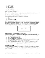
This menu contains selections to perform the following:
•
Test the VFD display, front panel LEDs, and control knob
•
Test the system internal device control bus
Front Panel Diagnostic Tests
This selection starts a non-destructive system test that exercises all pixels on the VFD display, changes the VFD
display brightness through all available settings, tests the LED on each front panel button, requests the operator to
turn the control knob and observe the display changes, and tests the various on-board intelligent devices. The control
knob should change smoothly and display values between 0 and 511. All pixels on the VFD display should illuminate
as should the front panel LED’s. The test takes a few minutes and cannot be terminated until it completes.
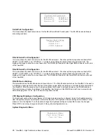
I2C Bus Diagnostic Tests
This selection starts a non-destructive system test that verifies the operation of the internal data bus used to control
the input video decoder, the Genlock decoder, the output video encoder, the non-volatile memory storage device, and
the input video mixer (ViewMAX-PRO only). The tests takes a few minutes and cannot be interrupted. PASS should
be displayed for all listed devices.
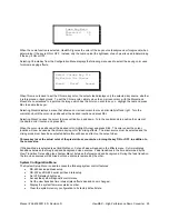
View Transitions
This menu option allows the time between view, pan, zoom, and fade updates to be configured. The default is 1
second, but this can be changed from 0 to 9.5 seconds in 25 millisecond steps. Small values will result in abrupt
transitions from one configuration setting to the next. Larger values result in a smooth camera-like transition from
one configuration to the next.
System Reset
This menu option allows the system non-volatile memory to be reset to its initial factory configured state. All saved
view settings, input video format edge adjustments, brightness settings, etc. will be reset. A confirmation message
will be displayed to allow the user to accept or cancel this operation.
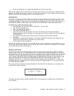
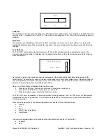
Output Picture Adjustments (Test Patterns Must Be On)
Selecting PICT ADJ when test patterns are enabled displays the following menu used to adjust the analog video
output encoder. Hue will not be displayed if PAL is selected as the video output format.
These adjustments do not
affect D1/SDI digital output.
Picture Adjustments when test patterns are displayed (affects output encoder)
•
Brightness Control (0 to 94 mV in 1 mV steps) 0 mV is nominal default
•
Contrast Control (78.0% to 130.0% in 1% steps) 100% is nominal default
•
Hue Control ( -21.0 degrees to +23.0 degrees in 1 degree steps) 0 degrees is nominal default (NTSC only)
•
Saturation Control (78.0% to 130.0% in 1% steps) 100% is nominal default (changes both the U and V
control registers simultaneously and sets both to the same value)
•
Pedestal Control (On or Off, NTSC only) adds 7.5 IRE pedestal for NTSC output. Default is On for NTSC.
•
ResetAll restores factory defaults for the picture adjustments controlled by this menu
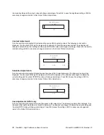
Brightness Adjustments
Turn the control knob to highlight Brightness and then press SEL. The following control will be displayed. Turn the
knob to the right to increase the brightness or to the left to decrease brightness. The slide bar will change to indicate
Output Picture Adjust
Brightness Contrast
Hue Sat
Pedestal ResetAll


