


Manual # 26-6090901-00 / Revision D
ViewMAX – High Performance Down Converter 7
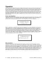
Video Input Connections
The video input section on the rear panel consists of a DB-15 Female input connector and a similar loop-through
connector (VIDEO IN and VIDEO LOOP).
1)
The default video input source is Analog RGB. For HDTV input it may be necessary to select Analog YUV
as the input source. If a Digital Visual Interface card is installed, you will need to select the DVI input
source. See Section 6 for configuring the input source via the front panel.
2)
To connect to a workstation or PC with an analog 15-pin VGA connector, connect the video output of the PC
to the VIDEO IN connector on the rear panel. To view the video output on a computer monitor, connect the
monitor to the VIDEO LOOP connector on the rear panel. If the image is too dim, too bright, or not visible,
press the Hi-Z/75 Ohm termination switch located to the right of the VIDEO LOOP connector and use the
best setting. Note: it is not possible to view the analog video source input on the VIDEO IN connector by
connecting a monitor to the digital DVI-D LOOP connector.
3)
To connect a workstation or PC with a Digital Visual Interface (DVI) connector, connect the video output
from the computer to the DVI-D IN connector on the rear panel. To view the output of the computer video on
a digital monitor, connect a cable from the DVI-D LOOP connector on the rear panel to the digital monitor.
Note: it is not possible to view the digital video source input on the DVI-D IN connector on the analog
VIDEO LOOP output. Depending on the DVI video source, a video monitor may be required to be connected
to the DVI LOOP connector and be powered on prior to booting the source computer to enable the video
source’s DVI output. ViewMAX only provides for a DVI video loop output.
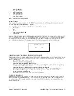
Video Output Connections
RGB/Betacam (YUV) Video Output:
Connect the output device to the set of BNC connectors marked R/V, G/Y and
B/U on the output section of the ViewMAX rear panel (see Figure 5-0). Select the desired output format via the front
panel menus or RS-232 link.
Y/C Video Output:
The Y/C video output connector is a 4-Pin Mini DIN located on the rear panel of the ViewMAX
(see Figure 5-0). Using a commercial S-VHS cable, connect the Y/C video output to the input of the S-VHS device
(monitor, video recorder, etc.).
Composite Video Output:
Connect the composite input of the monitor to the composite output BNC (COMP) of the
ViewMAX using a 75 ohm coaxial cable.
Digital Video Output (optional):
Connect a cable to the right-most BNC connector (D1) on the upper row of
connectors on the rear of the ViewMAX
Output Sync Connections
Two different types of output synchronization signals are provided by ViewMAX:
A. Synchronization
signal provided on the each R/G/B video output (Sync-on-Green).
B.
A composite synchronization signal (CSYNC).
Follow the instructions below to configure ViewMAX to provide the required type of output sync.
A.
Sync on Green: No additional connections are required. Make sure to set
Sync on Green
to
ON
from the PICT ADJ
Æ
More…
Æ
OFmt
Æ
SynGrn Menu if SOG is
required.
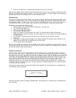
B.
Composite Sync: Connect the composite sync from the output BNC labeled CSYNC to the output
device.
Note: No sync connections are required if digital video is being utilized to drive the output device


