Operating Manual EMGZ309._.EIP
13
4.8
Calibration over the Operating Panel
1.
Load a rope with a defined weight corresponding to your calibration force on the
roller. The roller configuration must correspond to the real configuration in the
machine (wrap angle, distance of the rollers etc.).
2.
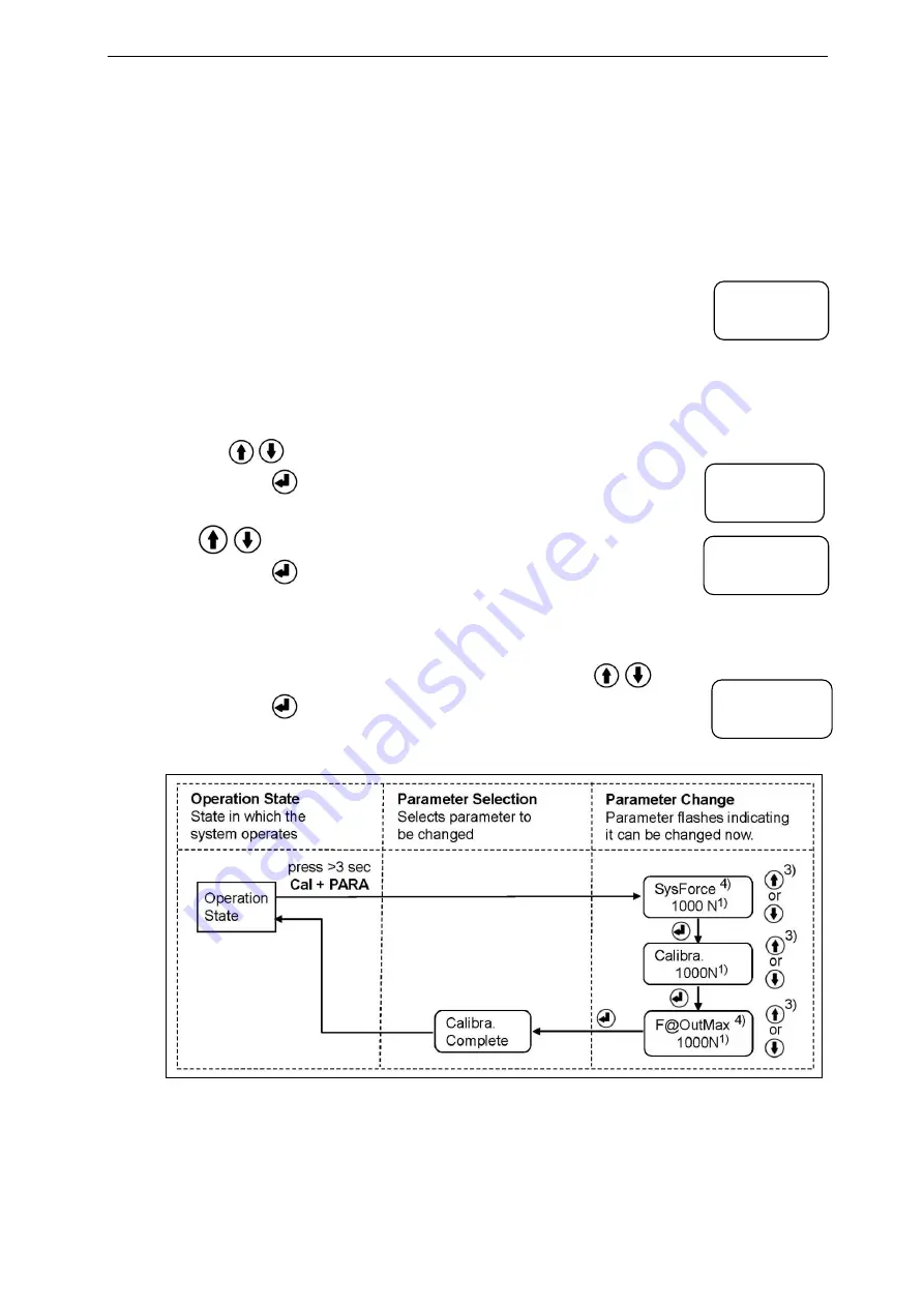
The calibration mode can be entered by pressing the two keys Cal and PARA at
the same time for longer than 3 seconds. Display changes to
The System Force [SysForce] determines the measuring
capability of your measuring roller. E.g. if two 500 N sensors are
installed in the measuring roller, enter 1000N. If only one 500N sensor is used,
enter 500N (see 8.3 “Descriptions of Parameter”, [SysForce]).
3.
The parameter [SysForce] flashes indicating that the force can now be changed.
Use
keys to enter the system force.
4.
Press the
key to confirm your input. Display will change to
5.
Enter the force corresponding to your calibration weight with the
keys.
6.
Press the
key to confirm your input. Display will change to
7.
With the parameter [F@OutMax] the force corresponding to the maximum
amplifier output (10V or 20mA) can be assigned (see 6.3 “Descriptions of
Parameter”, [F@MaxOut]). Enter the value with the
keys.
8.
Press the
key to confirm your input. Display will change to
The calibration procedure has been completed successfully.
Fig. 8: State diagram calibration
E
MGZ309015e
1)
The display shows the unit of measure that was previously selected.
3)
Permanent key pressing expedites the changing speed.
4)
If the Device Mode [VoltGauge] is set, these parameters are deactivated
SysForce
1000.0 N
Calibra.
1000.0 N
F@OutMax
1000.0 N
Calibra.
Complete


