www.fmiproducts.com
116647-01H
7
PRE-INSTALLATION PREPARATION
Continued
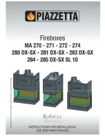
Figure 4 - Framing Clearances for
Installation Against an Exterior Wall
32
3
/
8
"
34
5
/
8
"
17" (Horiz. Vent)
20" (Vert. Vent)
Figure 5 - Framing Clearances for Corner
Installation
A
B
E
F
G
H
D
C
Nailing Tabs
28
1
/
2
"
13
5
/
8
"
39
3
/
8
"
10
3
/
8
"
9
7
/
8
" 34
3
/
8
"
34
5
/
8
"
54
1
/
8
"
Nailing
Tabs
C
B
A
D
E
F
G
Top of Louver Opening
3
2
1
4
5
6
7
Wall
Figure 6 - Clearances for Combustible
Mantels
Ref.
Mantel
Depth
Ref.
Mantel from Top of
Louver Opening
1
14"
A
16"
2
12"
B
14"
3
10"
C
12"
4
8"
D
10"
5
6"
E
8"
6
4"
F
6"
7
2"
G
4"
NOTICE: This fireplace is in
-
tended for use as supplemental
heat. Use this fireplace along
with your primary heating sys
-
tem. Do not install this fireplace
as your primary heat source.
If you have a central heating
system, you may run system’s
circulating blower while using
fireplace. This will help circulate
the heat throughout the house.
In the event of a power outage,
you can use this fireplace as a
heat source.
FRAMING AND FINISHING
Figure 4 shows typical framing of this fire
-
place. Figure 5 shows framing for corner
installation. All minimum clearances must
be met.
For available accessories for this fireplace,
see
Accessories
on page 40. If you are using
a separate combustible mantel piece, refer to
Figure 6 for proper installation height. You can
install noncombustible mantels at any height
above the fireplace.
Note
: Noncombustible
mantels may discolor!