


Installation
Inputs and Outputs
39
5
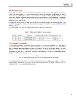
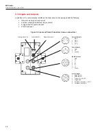
Table 5-4: Current Outputs, 4 pins
Description
Color
1
IGND
common ground connection for all current outputs,
electrically isolated to the GND ground
brown, pink, gray
2
OUT1
current output 1
yellow
3
OUT2
current output 2
green
4
OUT3
current output 3
white
shield
black
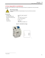
Table 5-5: Power Supply, 3 pins
Description
Color
1
GND
power ground
brown
2
not connected
3
+ 24 VDC
input for + 24 VDC power supply voltage
white
shield
black
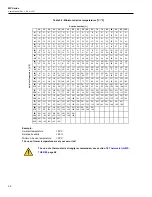
Table 5-6: RS485 Interface, 7 pins
Description
Color
1
GND
Ground, (connected to power ground)
gray
2
T+
RS485 transmit
brown
3
T-
RS485 transmit
white
4
R+
RS485 receive
green
5
R-
RS485 receive
yellow
6
n.c.
7
+ 12 VDC
regulated voltage for the RS232/485 converter
pink
shield
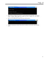
Table 5-7: Alarm and Trigger, 6 pins
Description
Color
1
Relay contact
Potential free relay contact, capacity max. 30 V, 1 A
brown
2
Relay contact
Potential free relay contact, capacity max. 30 V, 1 A
white
3
T
Trigger input: + 5 to + 24 VDC
green
4
Trigger -
Trigger input GND
yellow
5
Functional input
max. + 5 VDC
pink
6
Functional input
GND
gray
shield
black
Содержание MP Series
Страница 16: ...MP Series Users Manual Rev 1 0 Apr 2021 16 1024 pixel 80 Hz scan rate Scan Angle FOV All models 90 ...
Страница 18: ...MP Series Users Manual Rev 1 0 Apr 2021 18 2 2 1 2 Far Focus Figure 2 2 Optical Diagrams Far Focus ...
Страница 37: ...Installation Ethernet 37 5 5 Close the dialog box by pressing on Save ...
Страница 44: ...MP Series Users Manual Rev 1 0 Apr 2021 44 7 2 Mounting Plate A MP MP Figure 7 1 Mounting Plate for Tripod ...


