


Using The Bushealth Function
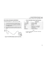
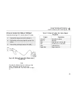
Input Connections and Tested Signals
6
77
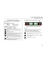
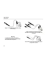
Profibus DP/RS-485
Default probe setting 10:1. Use the Fluke 10:1 probes.
1
Connect the red probe to the test tool input A
and the grey probe to input B.
2
Connect the ground lead of the input A probe to
the DP bus RxD/TxD N (-)
3
Connect the ground lead of the input B probe to
the DP bus cable shield.
4
Connect the probe tip of both probes to the DP
bus RxD/TxD P (+)
DATA +
DATA -
DATA GND
Figure 43. Profibus DP Measurement Connections
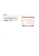
Table 9. Profibus DP Tested Signal Properties
Signal Description
V-Offset
V offset
V-Level Peak-peak
voltage
Data
Bit
width
Rise
Rise time as % of bit width
Fall
Fall time as % of bit width
Jitter Jitter
distortion
Signal Dist.
Overshoot
Signal distortion (Manchester
decoding, default setting)
Overshoot (NRZ decoding, can be
selected via limit setup)
Note
The bus normally has continuous data traffic.
Содержание 19xC
Страница 2: ......
Страница 9: ...Contents continued v A Bushealth Measurements A 1...
Страница 10: ......
Страница 36: ...Fluke 19xC 2x5C Users Manual 26...
Страница 60: ...Fluke 19xC 2x5C Users Manual 50...
Страница 110: ...Fluke 19xC 2x5 Users Manual 100...
Страница 146: ...Appendices Appendix Title Page Bushealth Measurements A 1...
Страница 147: ......


