background image

  QS204215 Rev B 


9  

|


IMPORTANT MOUNTING GUIDELINES 
 

1.  Never mount the sensor at an angle. 
2.  Liquid should never enter the dead band. 
3.  Mount sensor at least 3” from the side wall. 
4.  Never mount the sensor in a vacuum. 
5.  Do not obstruct the sensor’s beam width. 


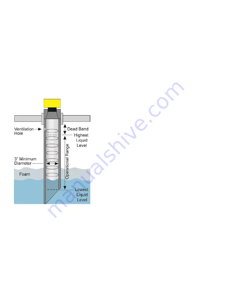
MOUNTING IN STAND-PIPE 
 

A stand-pipe may be used to dampen turbulence, separate surface foam from the point of measurement or 
increase performance in heavy vapor.  When mounting the sensor in a stand-pipe, the minimum diameter of 
the pipe is 3”.  Larger diameter pipes can be used.  The pipe should be attached with a coupling and reducer 
bushing.  The pipe length should run the measurement span and the bottom of the pipe should remain 
submerged at all times to prevent foam from entering the pipe.  Cut the bottom end of the pipe at 45° and drill 
a 1/4”pressure equalization hole high in the sensor’s dead band.  Locate the stand-pipe away from pump 
outlets and/or other sources of substantial turbulence which might cause the liquid in the pipe to oscillate. 


Содержание EchoPod DL34 Series

Страница 1: ...t Los Alamitos CA 90720 p 562 598 3015 f 562 431 8507 w flowline com QS204215 Rev B DL34 00 Shown 2019 Flowline Inc All Rights Reserved Made in USA DL34 Series Quick Start EchoPod Ultrasonic Liquid Level Switch Controller Transmitter ...

Страница 2: ...sing EchoPod The sensor provides level measurement switching and or control for your tank application This Quick Start includes everything you ll need to get the sensor up and running COMPONENTS Depending on the sensor part number configuration that was shipped EchoPod comes with a 4 1 2m cable Viton gasket for installation and the Quick Start Some models have the USB Key Fob LI99 2001 included wi...

Страница 3: ... required drivers STEP 2 CONNECT THE USB FOB NOTE Do not connect the Fob until after you ve installed WebCal The sensor communicates to WebCal through the USB Fob Prior to plugging the Fob into your computers USB port ensure that all external power is disconnected from EchoPod The maximum distance between the computer and EchoPod is 15 1 Connect the red green white and black wires from the EchoPod...

Страница 4: ...nfigures the relays in terms of pump valve operations as well as high or low alarms b Sets fail safe for the relays and the sensor s output current voltage or frequency 2 Tank Shape Selection a Defines the shape of the tank as well as the dimensional information for the tank with respect to the sensor s location on the tank 3 Tank Level Configuration a Enters the settings for the relay activation ...

Страница 5: ...es the shape of the tank as well as the dimensional information for the tank with respect to the sensor s location on the tank TANK LEVEL CONFIGURATION Enters the settings for the relay activation points as well as confirms the operational range ...

Страница 6: ... software please refer to the WebCal manual located at flowline com webcal software Before configuration can be completed You must click the Write to Unit button to save the settings to the unit Then click Wiring Diagram for a hard copy of the sensor s settings Finally enter the file name under which you wish to save the configuration file and click Save Config File Configuration is now complete D...

Страница 7: ...ngineering The more commonly used Advanced features are the Invert Relay and Increase Output Filtering described below Increase Output Filtering Placing a check mark in the box will additional filtering to the 4 20 mA output Decrease Output Filtering Placing a check mark in the box will remove all output filtering on the 4 20 mA output Invert Relays Placing a check mark in any of the four boxes wi...

Страница 8: ...m Mounting with a Tank Adapter Select a tank adapter fitting such as the LM52 2890 Mounting in Riser As installations with tall narrow risers can impede the acoustic signal 2 diameter risers should be no taller than 4 Larger diameter risers should be no taller than 12 Mounting in Side Mount Bracket Use Flowline s LM50 1001 side mount bracket LM50 1001 Shown Note The Side Mount Bracket LM50 series ...

Страница 9: ...n heavy vapor When mounting the sensor in a stand pipe the minimum diameter of the pipe is 3 Larger diameter pipes can be used The pipe should be attached with a coupling and reducer bushing The pipe length should run the measurement span and the bottom of the pipe should remain submerged at all times to prevent foam from entering the pipe Cut the bottom end of the pipe at 45 and drill a 1 4 press...

Страница 10: ...ew communication and should not be connected during usage in the application These wires should not be connected to WebCal while power is supplied from any source other than the LI99 series Fob The maximum cable distance between the computer and EchoPod is 15 Note Never allow the white or green wires to touch any power supply Blue Orange Yellow Purple Blue Rly1 Orange Rly2 Yellow Rly3 Purple Rly w...

Страница 11: ... Supply voltage should never exceed 28 VDC Do not exceed 28 VDC power on the relays within EchoPod Always use stepper relays between the sensor and external loads For DC circuits use a catch diode such as 1N4148 shown above Protect the sensor from excessive electrical spikes by isolating the power whenever possible The sensor materials must be chemically compatible with the liquids to be measured ...

Страница 12: ...e 2 have been subjected to electrical mechanical or chemical damage due to improper accidental or negligent use 3 have been modified or altered 4 anyone other than service personnel authorized by Flowline have attempted to repair 5 have been involved in accidents or natural disasters or 6 are damaged during return shipment to Flowline Flowline reserves the right to unilaterally waive this warranty...

Отзывы: