background image

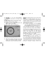
selection by pressing the red knob.

The next step is to synchronise the position of the
bridge hut in the display with the actual current
position of the bridge hut on the turntable on the
layout

In menu option CnF, rotate the red control
knob 
until the bridge is in the current
position.

Press the red knob to confirm this selection.

The display will now automatically switch to the
SEL menu option. 
Now you will be able to access all bridge
positions  "step by step" (with each rotation of the
red knob, the bridge will turn to the next available
track exit, or rest setting) in accordance with the
way you have turned the red knob.

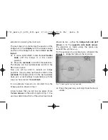
In our example, however, we will start from the
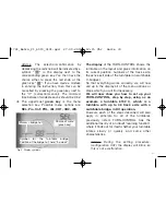
bridge position shown in Fig. 7.

A new feature that you will now be aware of are
the two arrows on the bottom right of  Fig. 7. You
can now determine which of the active track ends

should be live – either the bridge hut side (left
arrow) 
or on the opposite side (right arrow).
The selection is made using the green key
beneath the symbol <-->.
For the purpose of our example, we will select the
left side (=  bridge hut side as the live side). 

Press the green key until only the left arrow is
visible. 

35

<  >

-  -

Fig. 7  Selecting the live track end side

1721_Betra_21_6915_0101.qxd  27.09.2007  12:15 Uhr  Seite 35

Содержание TURN-CONTROL

Страница 1: ...lin 7286 either in DC powered or digital systems and even in 3 rail AC layouts so that you can pre select your desired turntable exit tracks and automatically rotate the turntable to them The TURN CON...

Страница 2: ...ipping Advice on Use The TURN CONTROL requires a separate power source transformer not included in delivery In the interests of safety in operation as well as the enjoyment of the equipment itself ple...

Страница 3: ...nstruction from the company of M rklin Art No 7286 1 2 Components operational elements and connections First of all please check through the components of your TURN CONTROL as delivered The components...

Страница 4: ...tions and turntable connections are made via the 7 pole plug The location of the wires can be seen above Fig 2 or shown on the rear of the equipment and are decribed in the following chapter Connect u...

Страница 5: ...ayout In principle the TURN CONTROL is suitable for all model railway systems whether 2 rail or 3 rail We will separate the 2 rail systems into analog standard DC operation and digital operation Altho...

Страница 6: ...yellow wire from the turntable is connected to socket 7 B For connecting up a FLEISCHMANN turntable 6652 for 3 rail AC operation M rklin system here are the plug connections The two wires from the tr...

Страница 7: ...tinuous between 14 volts and 16 5 volts 2 2 Connection to a transformer Using the connecting cable supplied 39 6865 connect the free ends of the wires onto a the continuous AC output 14 16 5 V or b th...

Страница 8: ...orrectly To operate your TURN CONTROL there are certain operational controls The red rotating knob This has 2 operational functions Rotation and Depression Rotating the knob brings up the next step in...

Страница 9: ...that everything works correctly we will now call up in the display all of the menu options or steps which you will find necessary We will now show you how to set up your TURN CONTROL step by step usi...

Страница 10: ...appears To confirm your selection press the red knob once The TURN CONTROL now knows that your turntable has 48 possible track exits As we are using a switchable C bridge in our example we must now t...

Страница 11: ...e next available track exit or rest setting in accordance with the way you have turned the red knob In our example however we will start from the bridge position shown in Fig 7 A new feature that you...

Страница 12: ...In our example the first track exit is in the position at 9 o clock with the bridge in the correct position Advice If not turn the red knob to the desired position so that the bridge symbol in the dis...

Страница 13: ...mbered In the same way we can now put the next track exits Nos 2 to 4 into the TURN CONTROL Advice Once you have no further track exits to put in then you can get out of the programming menu Pro by pr...

Страница 14: ...The track exit number 02 has now been put in and remembered After this step your display should look like that shown in Fig 12 The third step is just the same as the second Turn the red knob until th...

Страница 15: ...reached the position of the fourth track exit as in our example at 3 o clock Fig 14 Confirm After turning the red knob again a new tiny strip will appear beside the bridge hut symbol Confirm Turn the...

Страница 16: ...ays be shown with the individual programmed exit numbers We have now told the TURN CONTROL all it needs to know about the tasks it has to perform so we can now proceed to the next section on how to us...

Страница 17: ...ack exit the number of this exit will also be displayed The active exit section will blink In the case of an emergency when you need to bring your turntable to a halt straight away then in the SEL men...

Страница 18: ...key alongside the already mentioned menu options CnF SEL and Pro you will also find the menu options POL CH1 CH2 rEL and rES CnF You have already discovered the CnF menu Configuration at the beginning...

Страница 19: ...polarity the symbol will be shown when the bridge hut is moved over that position This additional indication will remain in the display until the bridge hut has completed a complete half turn changin...

Страница 20: ...ng of the key or similarly press the key and hold it down when the sequence of menu options will be displayed one after the other at 0 5 second intervals as long as you keep the key pressed Pro CnF PO...

Страница 21: ...nd 1 LocoNet found 2 DCC found 3 LocoNet and DCC found rES ATTENTION With the Reset menu rES you will set the equipment back to its settings as delivered All of your input data will be erased Please c...

Страница 22: ...g the active side of the bridge then it will not rotate through 180 A 180 rotation of the bridge left or right can be started with the electrical accessory address 200 red right clockwise green left a...

Страница 23: ...annot start an erroneous rotation This way you have 99 possible track exit numbers at your disposal by using different numbers on different turntables by use of several TURN CONTROL units you can remo...

Страница 24: ...For controlling the adresses 200 to 299 are to be used the data format is DC Refer to TWIN CENTER under Basic settings switch settings of dig addr of virtual electrical accessory decoders see TWIN CE...

Отзывы: