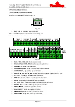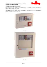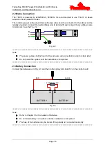
FlameStop FDCIE Panels With AS4428.3-2010 Fascia
Installation and Operation Manual
Page 8
at the access level 2. The 003 key is not removable in access level 2
1.4 Configuration and Functions
1.4.1 Internal Components
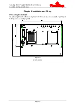
The internal construction of the small version FDCIE cabinets is shown in Fig. 1-2.
Fig. 1-2
1.4.2 Configuration and Functions of PFS116-AUS and PFS116-AUS-LRG
PFS116-AUS / PFS116-AUS-LRG control panels have the following configuration and functions.
Circuit Breaker: Open/Close the main power source of the FDCIE.
Batteries: Standby power source for the FDCIE.
Control board: For controlling power supply, charger, and all outputs such as
fault/disable/supervisory relay output, alarm output, sounder outputs and repeater panel
for zone 1 to 8, and monitoring the state of zone 1 to 8.
Extension board: Providing detection input and repeater output for zone 9 to 16.
Display board: For information display and key operation.
Manual Call Point: A device can go into fire alarm when it is pressed.
Relay board (optional): Providing detection input and repeater output for zone 9 to 16.
Controlling outputs of alarm relay and fault relay for zone 1 to 16.
1.4.3 Configuration and Functions of PFS108-AUS and PFS108-AUS-LRG
PFS108-AUS / PFS108-AUS-LRG control panels have the following configuration and functions.
Circuit Breaker: Open/Close the main power source of the FDCIE.
Batteries: Standby power source for the FDCIE.
Control board: For controlling power supply, charger, and all outputs such as
fault/disable/supervisory relay output, alarm output, sounder outputs and repeater panel
for zone 1 to 8, and monitoring the state of zone 1 to 8.
○
1 Display board
○
2 Manual call point
○
3 Optional relay board or zone
extension board for 16 zone
panel
○
4 Control board
○
5 Batteries
○
6 Circuit breaker
5
4
3
1
2
6


