background image

FlameStop FDCIE Panels With AS4428.3-2010 Fascia


Installation and Operation Manual


Page II 

2.5 Sounder Output Connections ......................................................................................... 18


Chapter 3 System Setup ....................................................................................................... 19


3.1 Setting Access Levels .................................................................................................... 19


3.1.1 Setting Access Level I .............................................................................................. 19


3.1.2 Setting Access Level II ............................................................................................. 19


3.1.3 Setting Access Level III ............................................................................................ 19


3.2 Setup of the Sounder / Alarm Output ............................................................................. 20


3.3 Disablement of a Zone or Output ................................................................................... 21


3.3.1 Use of Disablement Function ................................................................................... 21


3.3.2 Operation Basic Steps. ............................................................................................ 21


3.3.3 Quick Disablement Function. ................................................................................... 21


3.4 Setting Test Mode .......................................................................................................... 22


3.4.1 Use of Test Mode ..................................................................................................... 22


3.4.2 Operation Steps ....................................................................................................... 22


3.5 Programming Output Modes .......................................................................................... 23


3.5.1 Setting Zone “With Manual Call Point” ..................................................................... 23


3.5.2 Setting Associated Sounders to a Zone ................................................................... 24


3.5.3 Setting Delay Time of Alarm Output ......................................................................... 25


3.5.4 Sounder Output Mode ............................................................................................. 25


3.6 Supervisory Mode

 .......................................................................................................... 27


3.6.1 Use of Supervisory Function .................................................................................... 27


3.6.2 Programming a Zone to Supervisory ....................................................................... 27


3.7 Setting Auxiliary Functions ............................................................................................. 28


3.8 Ground Fault Detection .................................................................................................. 28


3.9 Auxiliary Power Setting .................................................................................................. 28


3.10 Restore Default Settings .............................................................................................. 29


Chapter 4 Operation Instructions ......................................................................................... 30


4.1 Working State Description .............................................................................................. 30


4.1.1 State of Detection Zones ......................................................................................... 30


4.1.2 Alarm Output State ................................................................................................... 30


4.1.3 Sounder Outputs State ............................................................................................ 30


4.1.4 Safe State ................................................................................................................ 30


4.1.5 Description of the Buzzer ......................................................................................... 31


4.1.6 Others ...................................................................................................................... 31


Содержание PFS102-AUS

Страница 1: ......

Страница 2: ......

Страница 3: ...reactivate the warning system FIRE MODE DISABLING To disable zones in fire mode press SILENCE RESOU zones that have been activated in fire mode DISABLING ZONES Press the DISABLE ENABLE button Use the...

Страница 4: ......

Страница 5: ...ions 8 1 4 1 Internal Components 8 1 4 2 Configuration and Functions of PFS116 AUS and PFS116 AUS LRG 8 1 4 3 Configuration and Functions of PFS108 AUS and PFS108 AUS LRG 8 1 4 4 Configuration and Fun...

Страница 6: ...Test Mode 22 3 4 2 Operation Steps 22 3 5 Programming Output Modes 23 3 5 1 Setting Zone With Manual Call Point 23 3 5 2 Setting Associated Sounders to a Zone 24 3 5 3 Setting Delay Time of Alarm Outp...

Страница 7: ...w to Replace 5A Fuse 35 6 3 Troubleshooting 36 Chapter 7 Device Wiring Diagrams 37 7 1 Magnetic Door Holders 37 7 2 Alarm From A Dry Contact Relay 38 7 3 Fault From A Dry Contact Relay 39 7 4 Beam Det...

Страница 8: ...cation of the installation Consult with the appropriate authority having jurisdiction for confirmation of the requirements The FDCIE shall only be installed and serviced by specially trained fire alar...

Страница 9: ...complies with the following AS 7240 4 requirements Power Supply Functions AS 7240 4 Clause Power supply from the main power source 5 1 Power supply from the standby power source batteries 5 2 Charger...

Страница 10: ...manual call point connection sound modes sounder delay modes and output delay modes Three access levels settable via the key switch and the internal switch Reserved repeater panel interface for fire...

Страница 11: ...rm output Type voltage contact output normally open close contact output are available defaulted normally open contact output Contact capacity 1A 24VDC Output voltage 18VDC 28VDC Output current 300mA...

Страница 12: ...e Length not longer than 1000m 1 2 5 Input Interface RESET EVAC SILENCE input Type normally open contact input Recommended Wiring 2 core 1 0mm2 or above complying with local installation codes Recomme...

Страница 13: ...y zone defined as supervisory is activated It illuminates steadily when the supervisory sound is silenced IN TEST Yellow It illuminates steadily when any zone is in test condition MAINS FAULT Yellow I...

Страница 14: ...e silenced SILENCE RESOUND ALARM It is available in Access Level II In fire condition silence resound the sounders RESET It is available in Access Level II for resetting the control panel Note The war...

Страница 15: ...nsion board Providing detection input and repeater output for zone 9 to 16 Display board For information display and key operation Manual Call Point A device can go into fire alarm when it is pressed...

Страница 16: ...d monitoring the state of zone 1 to 4 Display board For information display and key operation Manual Call Point A device can go into fire alarm when it is pressed Relay board optional Controlling outp...

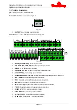
Страница 17: ...LT NC COM NO Fault output terminal DIS SUP NC COM NO Disable supervisory terminal ALARM Alarm output terminal SOUNDER OUTPUT 1 3 Sounder output terminals AUX SUPPLY Auxiliary power terminal REPEATER O...

Страница 18: ...REPEATER OUTPUT Z11 Z10 Z9 Z12 Z13 Z14 Z15 Z16 0V Fig 1 6 ZONE INPUT 9 16 Zone 9 to 16 input terminals Z9 Z16 Output terminals of repeater panel for zone 9 to 16 0V Power supply negative terminal for...

Страница 19: ...ter panel for zone 9 to 16 0V Power supply negative terminal for repeater panel connection FAULT1 FAULT16 Fault output terminals for zone 1 to 16 ALARM1 ALARM16 Alarm output terminals for zone 1 to 16...

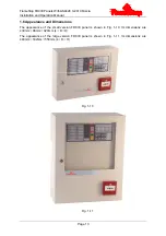
Страница 20: ...l Page 13 1 6 Appearance and Dimensions The appearance of the small version FDCIE panel is shown in Fig 1 10 Its dimensions are 430mm 98mm 320mm L D H The appearance of the large version FDCIE panel i...

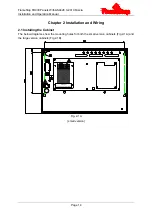
Страница 21: ...stallation and Operation Manual Page 14 Chapter 2 Installation and Wiring 2 1 Installing the Cabinet The below diagrams show the mounting holes for both the small version cabinets Fig 2 1A and the lar...

Страница 22: ...FDCIE Panels With AS4428 3 2010 Fascia Installation and Operation Manual Page 15 Fig 2 1B Large version Note Cable glands should be installed in the knock out hole to avoid cable abrasion and foreign...

Страница 23: ...ct the Live Brown wire to terminal L See the Fig 2 2 L N N G N Fig 2 2 Note The power cables shall be fixed to the enclosure using a restraint clamp for strain relief Do not power the system until the...

Страница 24: ...ximum amount of devices which can be connected to any single zone Also be sure to allow for all of the devices in your battery calculations talked about in Chapter 5 A 4 7k resistor is required at the...

Страница 25: ...nventional MCP s Fig 2 4 Fig 2 5 2 5 Sounder Output Connections All 24VDC sounders or remote devices are polarity sensitive and need to be connected with the correct polarity A 4 7k resistor shall be...

Страница 26: ...e set after the manual is read and understood 3 1 1 Setting Access Level I Turning CONTROL ENABLE lock to OFF shown as in Fig 3 1 the FDCIE is set to access level I Please be aware dip switch number 1...

Страница 27: ...Sounder Output 1 is a 24VDC voltage output Sounder Outputs 2 and 3 only have 24VDC voltage output modes Alarm Output X1 and Sounder Output 1 X2 are set as shown in Table 3 5 Table 3 5 Output Normally...

Страница 28: ...o 16 and the Sounder Outputs Please note the Alarm Output is not able to be Disabled 4 The AMBER LED for zones 1 to 16 will flash when the zone is to be selected Pressing the ENTER button will confirm...

Страница 29: ...s for testing that the detection zones operate correctly In this mode it tests if a zone can generate a fire alarm signal when it s manually activated into fire condition Alarm Output will not be acti...

Страница 30: ...regardless of any delay setting Basic steps are shown below 1 Enter access level III 2 Set the 2 of SW2 MCP ZONE on control board to ON position 3 Pressing the OUTPUT PROGRAM button the OUTPUT PROGRA...

Страница 31: ...y switch on or off their indicator The DISABLE ENABLE LED and TEST LED are used for setting up the output state of the selected Sounder Output to be an Immediate Delayed or No Output refer Chapter 3 5...

Страница 32: ...ds refer to Table 3 8 5 Pressing the ENTER button saves the current setting The FDCIE will sound for 1 second to indicate the successful setup 6 Pressing the CANCEL button will exit alarm output delay...

Страница 33: ...Continuous Output OFF Default Delay time can be obtained as shown in Table 3 8 Default setting is 0 seconds Table 3 8 Delay s 1 to 4 of SW3 DELAY TIME 1 2 3 4 0 OFF OFF OFF OFF 10 ON OFF OFF OFF 20 O...

Страница 34: ...toggle between zones 2 to 16 Flashing Green zone LED indicates the selected zone A steady illuminating green zone LED indicates the zone is already defined as a supervised 5 Pressing the TEST button...

Страница 35: ...ire condition for 3 minutes before the sounder outputs could be silenced If silence delay mode is turned off the sounder outputs can be silenced immediately Default setting is OFF TEST ZONE OUTPUT MOD...

Страница 36: ...Enter access level III 2 Pressing the OUTPUT PROGRAM button for at least 2 seconds the FDCIE gives 1 second sound indication to indicate a successful reset to factory settings 3 Exit access level III...

Страница 37: ...ULT LED should be off Fire If the alarm output is activated ALARM ROUTING ACTIVATED LED illuminates steadily Fault If the alarm output is in fault condition FAULT LED and ALARM OUTPUT FAULT LED flash...

Страница 38: ...r output delay will only work if all of the following conditions are met The sounder is associated with a zone and is programmed with delay refer 3 5 2 Zone has been set as No Manual Call Point refer...

Страница 39: ...button again will make them resound If the remote SILENCE input contact is shorted for over 2 seconds the FDCIE will silence the sounder outputs regardless of the current access level 4 5 Evacuation T...

Страница 40: ...total current in alarm state TA alarm load standby power source time normally 0 5 h 1 25 compensation factor for expected battery deterioration Where the load may vary the worse case average over requ...

Страница 41: ...FlameStop FDCIE Panels With AS4428 3 2010 Fascia Installation and Operation Manual Page 34 Battery Calculation Worksheet...

Страница 42: ...cing the Fuses There are two types of fuses in the FDCIE located on the control board and battery cable respectively as shown in Table 6 1 Table 6 1 Position Mark Rated value Control Board F1 2A 250VA...

Страница 43: ...ions B Replace the fuse F1 C Replace the control board D Check and reconnect the cable 2 Battery fault A Loose battery connection B 5A fuse is blown C The voltage of batteries is low A Check cable con...

Страница 44: ...FlameStop FDCIE Panels With AS4428 3 2010 Fascia Installation and Operation Manual Page 37 Chapter 7 Device Wiring Diagrams 7 1 Magnetic Door Holders...

Страница 45: ...rm From a Dry Contact Relay Hard Contact Device Connection Diagram to PFS1XX AUS Panels To generate an ALARM when the device is activated FIP ZONE 4 7K resistor 470 OHM NC C NO Commonly Used Hard Cont...

Страница 46: ...9 7 3 Fault From a Dry Contact Relay Hard Contact Device Connection Diagram to PFS1XX AUS Panels To generate a FAULT when the device is activated FIP ZONE 4 7K resistor NC C NO Commonly Used Hard Cont...

Страница 47: ...4 Beam Detector With Reflector PHI 9105R Beam Detector with Reflector The PHI 9105R beam detector with reflector can be used on both the FlameStop conventional and addressable fire alarm panels See PH...

Страница 48: ...FlameStop Australia Pty Ltd Address 1 70 Gibbes Street Chatswood NSW 2067 Phone No 02 9932 2020 Fax No 02 9932 2022 Email Address sales flamestop com au Website www flamestop com au...

Отзывы: