13
12
SPECIALIZED
HEALTHY
AIR SOLUTIONS
SPECIALIZED
HEALTHY
AIR SOLUTIONS
OWNER’S MANUAL
OWNER’S MANUAL
ASCENDANT
™
ASCENDANT
™
SPECIALIZED
HEALTHY
AIR SOLUTIONS
OWNER’S MANUAL
Heating and/or cooling coils can be ordered with the
energy recovery system. All necessary heating and/
or cooling coils have been installed at the FläktGroup
SEMCO factory. However, before operating them, a brief
pre-startup inspection is recommended.
INSPECTION
•
Inspect all pipe connections to verify they are tight
and that no damage has occurred during transit or
on-site installation.
•
STEAM COILS
– Be sure that the unit is level so the
coils inside the casing slope toward the header.
•
HOT WATER COILS
– Check the freeze protection
thermostat for proper operation so that it will
function to prevent freeze-ups.
OPERATION
•
STEAM COILS
– Non-freeze steam coils are
designed to operate steam pressures up to, and
including, 150 psig and temperatures to 350°F.
•
During initial operation, make sure that
condensate flows back to the headers. Check for
leaks.
•
HOT WATER COILS
- are designed to operate at
pressures to 150 psig, and temperatures to
366°F. Check for leaks during initial operation.
•
COOLING COILS
-
are designed to withstand
pressures to 200 psig. During initial operation,
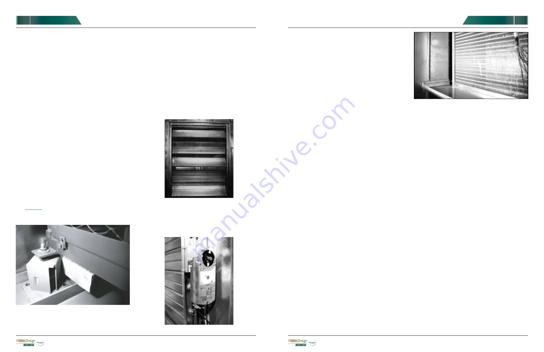
check for leaks (See
FIGURE 25
).
COILS
FIGURE 25.
Cooling coils should be checked for leaks during
operation.
3)
The dampers are controlled by electric motors.
Make sure that wiring is complete. Check the
wiring diagram on the motor.
4)
Turn on power and observe whether or not the
controls trigger dampers correctly. Be sure that
limit switches close when blades are open and
open when blades are closed.
AIR FILTERS
Air filters for the energy recovery system are boxed,
tagged and shipped loose inside the system for field
installation. This minimizes any risk for filter damage
during transit. The air filters must place installed prior
to startup or the warranty could be voided.
Throughout the operating life of the system, it will be
necessary to replace filters as they accumulate dirt
from the air stream.
The system is equipped with two pressure differential
gauges. As air filters accumulate dirt, the pressure
differential will rise.
The
PRE-FILTER CAPACITY AND RESISTANCE TABLE
(
FIGURE 26
) and
FINAL FILTER CAPACITY AND
RESISTANCE TABLE
(
FIGURE 27
) provide data for most
pre-filters and final filters used in FläktGroup SEMCO
systems. For each filter size, the pressure differential
(resistance at capacity) using new, clean air filters in
air streams is shown. The capacities columns define
airflow in cubic feet per minute. For specific airflows,
interpolating and estimating will provide adequate
data.
SPECIALIZED
HEALTHY
AIR SOLUTIONS
OWNER’S MANUAL
FIGURE 22.
As an option, the fans can be mounted on seismic
arrest mounts.
•
Rotate the impeller by hand; it should turn freely.
If not, check for obstructions and contact
FläktGroup SEMCO (see the
BACK COVER
for
contact info.).
•
Ensure that the fan wheel and fan interior are
clean are free of debris.
•
Check fan set screw for tightness; re-tighten if
necessary.
4)
After completing inspection checks on motors and
fans, turn power on then off quickly. Power should
be on just long enough to start fan rotation.
5)
If fans start rotating in the wrong direction (See
ARROW ON THE BLOWER
) turn off power
immediately. To correct rotation, lock out power to
the unit feeder, and switch any two line power
wires. To change rotation of only an inverter driven
wheel and not the fans, switch any two VFD line
power wires.
6)
Using an amp probe or amp meter, check the
actual operating current of the motor to make
sure it is not being overloaded or underpowered.
The operating current must not exceed the
nameplate current.
7)
Allow the assembly to run for about an hour. During
this time, listen for any unusual sounds. To correct
noise problems, see
TROUBLESHOOTING
on
.
OPTIONAL FAN MOUNT
DAMPERS
While they have been installed and checked at the
FläktGroup SEMCO factory, a pre-startup inspection
is recommended to be sure that nothing has become
detached or damaged during shipment or on-site
installation.
INSPECTION
1)
Check blade rotation clearance. Verify that blades
open and close properly and rotate sufficiently.
If they do not, check for obstructions, broken or
bent blades, or loose linkage. Correct or repair as
necessary (See
FIGURE 23
).
FIGURE 23.
Be sure that damper blades open
and close properly and have sufficient rotation
clearance.
2)
Be sure that actuator arms and bars connecting
damper motors to control rods or shafts are tight.
(See
FIGURE 24
).
FIGURE 24.
Damper actuator.


