19
18
SPECIALIZED
HEALTHY
AIR SOLUTIONS
SPECIALIZED
HEALTHY
AIR SOLUTIONS
OWNER’S MANUAL
OWNER’S MANUAL
ASCENDANT
™
ASCENDANT
™
SPECIALIZED
HEALTHY
AIR SOLUTIONS
OWNER’S MANUAL
TROUBLESHOOTING
A failure in the drive can fall into one of two categories,
ALARM
or
FAULT
.
WHEN THE DRIVE DETECTS A FAULT:
•
The digital operator displays text that indicates the
specific fault and the
ALM
indicator LED remains lit
until the fault is reset.
•
The fault interrupts drive output and the motor
coasts to a stop.
•
It will remain inoperable until that fault has been
reset.
TROUBLESHOOTING THE WHEEL
MOTOR VFD
Burner safeties consist of:
•
Low gas pressure switch (located on the entering
side of the dual automatic safety shutoff valve)
•
High gas pressure switch (located on the leaving
side of the dual automatic safety shutoff valve)
•
Automatic reset airflow switch (located inside the
unit measuring air pressure drop across the burner
profile plate)
•
High limit (controller mounted inside the burner
control panel)
•
Flame rod - signal can be measured at Honeywell
R7847A Flame Amplifier port provided on the
Honeywell RM7895A Flame Relay. The flame rod
signal is 0 – 5.0 VDC, with 1.25 VDC volts minimum
required. Refer to Honeywell literature for detailed
information.
If the FläktGroup SEMCO controller is calling for heat,
and all safeties are made, then 120VAC power will be
delivered to terminal # 7 on the Honeywell flame relay.
If 120VAC power is not present, then trace the voltage
using the SEMCO electrical schematic. If voltage is
present but the burner does not light:
•
Is there air in the gas line?
•
Are the gas valves opening?
•
Measure the flame amplifier signal
•
Is the flamerod clean?
If you have additional questions, please contact
FläktGroup SEMCO Service at (573) 443.3636.
TROUBLESHOOTING THE DIRECT-FIRED
GAS HEATER
(ON APPLICABLE UNITS)
The basic troubleshooting strategy is to determine if
the problem resides with the program, controller, input
devices, outputs, wiring, or controlled device.
Check sensor input values using the BACview keypad
to confirm that all inputs are operating correctly and
values are as anticipated.
View setpoints using the BACview setpoint menu.
Compare setpoints to the design performance shown in
the unit submittal.
View outputs using the BACview setpoint menu to view
the output determined by the controller.
Measure the output at the controller, then at controlled
device and compare to the output calculated by the
controller. Are all controller outputs set to automatic?
Are inverters set to
AUTO
and
NOT HAND MODE
?
The controller has hand-off-auto capabilities which
can be useful for troubleshooting or for emergency
operation. For automatic operation, all output switches
on the controller should be to the left.
Manuals for the inverters and any gas-fired equipment
are shipped with the unit. Manuals for damper
actuators are available from the manufacturer's web
site. Condensing units for DX coils are provided by
other than FläktGroup SEMCO.
WHEN THE DRIVE DETECTS AN ALARM (MINOR FAULT):
The digital operator displays text that indicates the
specific alarm or minor fault and the
ALM
indicator LED
flashes.
•
The motor does not stop.
•
The digital operator displays text that indicates the
specific alarm or minor fault and the
ALM
indicator
LED flashes.
•
Remove the cause of an alarm or minor fault to
automatically reset.
In the event of an alarm or fault consult the Yaskawa
V1000 Technical Manual (page 241), also available
at www.drives.com, or contact FläktGroup SEMCO
Technical Service at (573) 443.3636 for assistance.
SPECIALIZED
HEALTHY
AIR SOLUTIONS
OWNER’S MANUAL
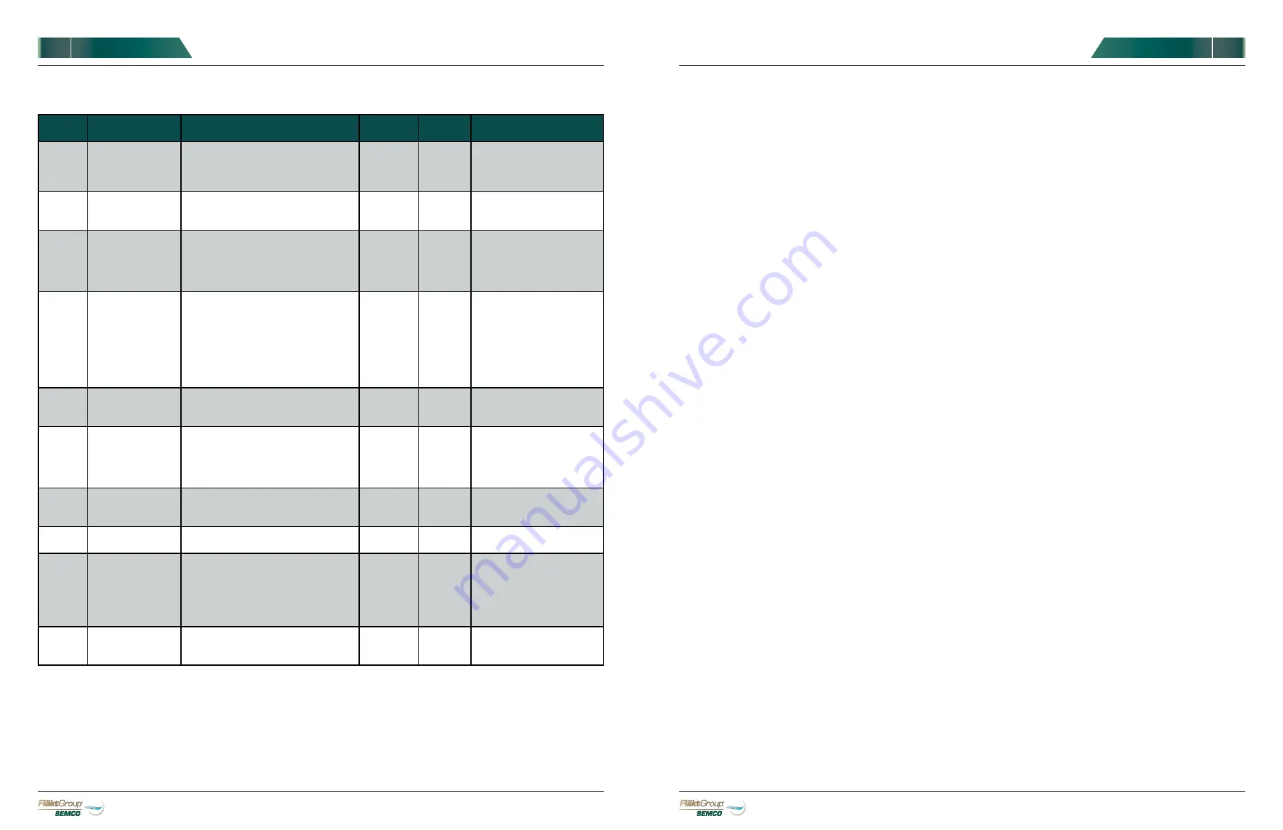
PARAM.
TITLE
FUNCTION
OPTIONS
DEFAULT
SETTING
SEMCO
SETTING
COMMENTS
H5-01
Drive Node
Address
0-20H
1F
*
Serial Communications
address
Set at factory. Consult
SEMCO
H5-09
CE Detection Time
0.0 - 10.0s
2
10
Sets the time required to
detect a communications
error.
L1-01
Motor Overload
Protection
0: Disabled
1: Std. Fan Cooled (speed range < 10:1)
2: Std. Blower Cooled (speed range
10:1)
3: Vector Motor (speed range 100:1)
1
3
Overload function based on
motor type
L2-01
Momentary Power
Loss Operation
Selection
0: Disabled - Drive trips on (Uv1) fault
when power is lost.
1: Power Loss Ride-Thru Time - Drive
restarts if power returns within the
time set in L2-02.
2: CPU Power Active - Drive will restart
if power returns as long as the CPU
is working.
0
1
Allows drive to restart after
power loss without a fault
L3-01
Stall Prevention
Level during
Acceleration
0: Disabled
1: Enabled
2: Intelligent Stall Prevention
1
0
Disables stall prevention
during acceleration
L3-04
Stall Prevention
Level during
Deceleration
0: Disabled
1: General Purpose Stall Prevention
2: Intelligent Stall Prevention
3: Stall Prevention with Braking Option
4: Over excitation Braking
1
0
Disables stall prevention
during deceleration
L3-05
Stall Prevention
Level during Run
0: Disabled
1: Decelerate Using C1-02
2: Decelerate Using C1-04
1
0
Disables stall prevention
during run
L5-01
Number of Auto
Restart Attempts
0 to 10
0
5
Selects number of automatic
restart attempts after fault.
L8-05
Input phase loss
protection
0: Disabled
1: Enabled
1
0
Selects the detection of
input current phase loss,
power supply voltage
imbalance, or main circuit
electrolytic capacitor
deterioration.
L8-07
Output phase loss
protection
0: Disabled
1: Enabled
2: Enabled
0,1
0
Selects the output Phase
loss detection


