23
22
SPECIALIZED
HEALTHY
AIR SOLUTIONS
SPECIALIZED
HEALTHY
AIR SOLUTIONS
OWNER’S MANUAL
OWNER’S MANUAL
ASCENDANT
™
ASCENDANT
™
SPECIALIZED
HEALTHY
AIR SOLUTIONS
OWNER’S MANUAL
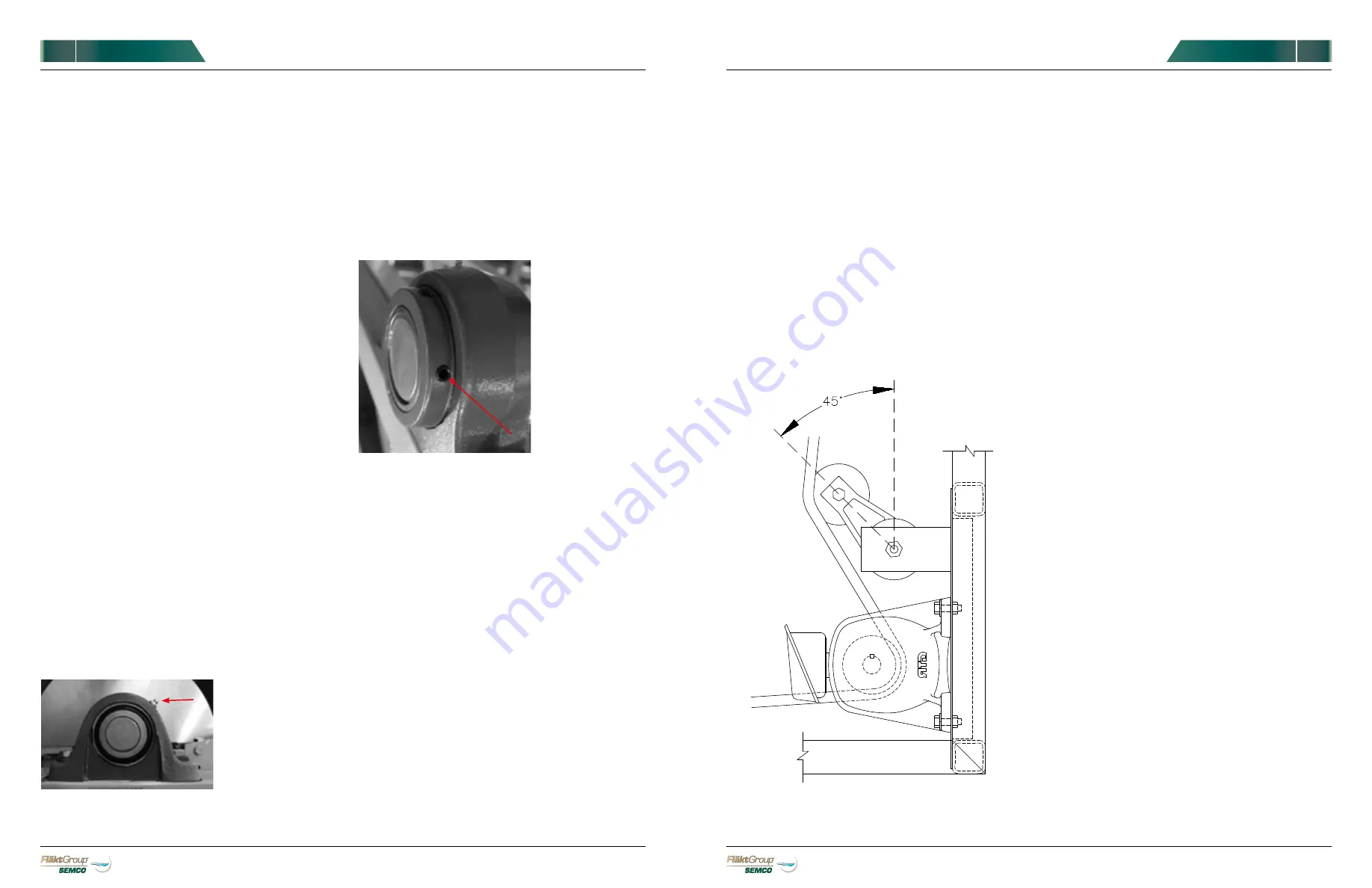
FIGURE 31.
Detail of TE-1567 R0 Idler
VARIABLE FREQUENCY CONTROLLER
1)
The variable frequency controller is cooled by
air flowing through the heat sink slots. The
slots must never be allowed to become
obstructed with dirt or foreign material.
Periodically check and clean the heat sink
slots with compressed air or a vacuum.
Airflow must never be restricted in any way.
2)
Check and clean the variable frequency
controller annually.
MEDIA CLEANING
Semi-annually, or more frequently if pressure drop
across the wheel increases at a given airflow, clean
wheel media by air blowing at 100 psi while using a
vacuum or other device to collect any dust or debris
that may exit the other side. Extra care should be
taken to ensure that the air nozzle or vacuum/other
device does not touch or damage the rotor surface.
SEALS
Seals should be checked to ensure they remain in
gentle contact with the wheel after the first month of
operation, and every 3 months thereafter.
NOTE:
If seals give any sign of binding the rotor, they should
be adjusted immediately.
Adjustment of the seals is simply done by loosening
the screws holding the seal clips in place, adjusting the
seal so it just contacts the surface of the wheel/rim,
and then re-tightening the screws.
holding the bracket to the perimeter, correct the
position, laterally and/or along the perimeter, so the
teeth now mesh, and reattach the bracket using #10 x
¾” tek screws.
CHAIN TENSION DETAIL
If the chain is excessively tight, chain damage and
gear motor failure may result. If the chain is too loose,
the chain may slip off the wheel sprocket(s). A good
rule of thumb for amount of slack is 2 to 4 percent of
the distance between the idler and the point where the
chain connects with the wheel.
The tensioner should be positioned so that after final
tensioning it is approximately at a 45 degree angle as
shown on
FIGURE 31
. Too little tension will limit the
effectiveness of the tensioner and too much may cause
premature chain failure.
TENSIONER ADJUSTMENT
1)
Loosen the tensioner by accessing the
mounting bolt from the back side of the
mounting bracket.
2)
Adjust the tensioner base by using a wrench
on the adjusting nut to load the tension spring.
3)
Tighten until chain has proper amount of
slack and preload tensioner spring. Utilize
tick marks on the tensioning arm and base
as a guide. After final tensioning the tensioner
should be able to move one full tick mark
when pulled to compress the spring (removing
chain tension).
SPECIALIZED
HEALTHY
AIR SOLUTIONS
OWNER’S MANUAL
MAINTENANCE: SYSTEM
The system enclosure requires very little maintenance
since it is constructed of strong, weather-resistant
materials. Equipment contained within the enclosure
requires regular maintenance to keep the system
operating smoothly. You will find maintenance
instructions for every component in this section.
•
Inspect the enclosure periodically:
•
Check for air leaks in the casing
•
Ensure modules remain level
•
Make sure that doors do not bind
•
Check around all penetrations and roof joints to be
sure that seals remain tight and do not leak
MAINTENANCE: WHEEL
ROTOR BEARING
The rotor bearing’s anticipated average life is 20 years.
The bearing was greased prior to shipment. However,
lubrication just prior to start-up is recommended.
RECOMMENDED LUBRICATION
The bearing’s lubrication cycle depends upon the range
of temperatures normally experienced by the unit 24
hours a day. For a typical temperature range of -20°F
to 130°F, lubrication every 6 months is adequate. If
higher temperatures (130° to 170°F) are experienced,
lubrication every 3 months is recommended. For
environments with temperatures above 170°F, consult
FläktGroup SEMCO.
Grease should be pumped into the 2 bearing grease
points - one located on each side of the rotor. (See
FIGURE 29
) A high grade NLGI No. 2 grease is
recommended.
NOTE:
If a rotor bearing requires
replacement, contact FläktGroup SEMCO for detailed
instructions.
FIGURE 29.
Grease
should be pumped
into two rotor bearing
grease points, one
located on each side
of the rotor. Lubrication
frequency depends
upon operating
temperatures normally
experienced around the
rotor.
FIGURE 30.
The
bearing set screws,
one on each side of
the rotor, should be
checked for tightness
every six months.
The bearing bolts normally require checking at start-up
only. The bearing bolts should be torqued to 50 ft-lbs.
BEARING SET SCREWS
1)
The bearing set screws should be checked
periodically for tightness. A bearing set screw
is located on each side of the rotor (See
FIGURE 30
).
RECOMMENDED CHECKING FREQUENCY
–
Bearing set screws should be checked at start-
up, one month after start-up, then every 6 months
thereafter.
2)
The bearing set screws should be torqued to 15 ft-lbs.
MOTOR
The motor has deep grooved, double-shielded bearings
with sufficient lubricant packed into the bearings by the
manufacturer for “life lubrication.” The initial lubricant
is supplemented by a supply packed into larger
reservoirs in the end shield at the time of assembly. No
grease fittings are provided as the initial lubrication is
adequate for up to 10 years of operation under normal
conditions. No lubrication is required.
WHEEL DRIVE SYSTEM
The chain and sprockets should be checked
periodically for wear and correct chain tension after
start-up and semi-annually thereafter. Although the
Ascendant wheel rotates at low speeds – less than
25 revolutions per hour – unnecessary wear can still
result from misalignment or improper tensioning.
DRIVE SYSTEM ALIGNMENT
At startup, observe the chain as the wheel rotates.
The chain should mesh with the teeth on the wheel
perimeter. If the teeth do not mesh, remove the screws


