


HyPower-Geko
Electrical connection
FläktGroup DC-2014-0022-GB 2018-05/R5 • Subject to modifications
91
6.12.5 Sensors and control inputs
Danger of electrical current!
Extra-low voltage terminal strip (sensor and control input) is not galvanically sepa-
rated from the mains supply voltage. Mains potential on terminal and terminal strip.
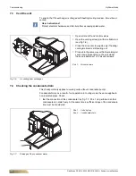
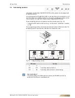
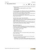
Fig. 6-83: Sensor connection
Room or return-air sensor connection (option) or inlet sensor
Pos. 1:
Room or return-air sensor
Pos. 2:
Inlet temperature sensor
•
Connect the sensors in accordance with the wiring diagram.
Return-air sensor:
– If a return-air sensor is connected, the switch CET.ACEC must be correspondingly
configured. You will find details in the separate operation manual of the switch
CET.ACEC.
– For wiring a factory-mounted return-air sensor, connect relevant CET.ACEC termi-
nals with the corresponding terminals in the unit terminal box (refer to the unit con-
nection diagram for terminals).
Inlet temperature sensor:
– Installation of inlet sensor in supply line
– Fixation of sensor with an enclosed clip on the pipe. The clip is suitable for pipe sizes
of 15 mm.
– Following sensor installation, restore the pipe insulation.
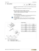
Room sensor:
– Fix the casing in a suitable place (see fig. 6-84) using appropriate screws (max. M4).
– Connect the room temperature sensor according to the wiring diagram.
CET
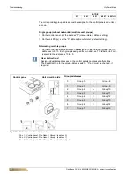
Fig. 6-84: Installation location
User instructions!
The installation site of the room temperature sensor is crucial for the pre-
cise control of room temperature. Therefore avoid mounting the sensor in
the following locations (refer to fig. 6-84):
– next to doors, windows, passageways etc., since intense movement of
air can cause incorrect measurements.
– Do not install on hot or cold walls (e.g. chimney, outside wall), since the
wall temperature can cause incorrect measurements,
– behind blinds and net curtains, as the insulating layers of air can cause
incorrect measurements.
– immediately near unit discharge grilles, since the discharge tempera-
ture can cause incorrect measurements.
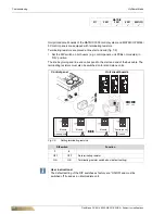
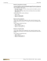
Fig. 6-85: Control inputs
Control inputs enable or H/C changeover
Pos. 3:
Input H/C changeover (instead of inlet sensor fig. 6-83, Pos 2)
Pos. 4:
Presence input (absent = contact closed)
Pos. 5:
Input enabling (active = contact open)
•
Connect the control inputs in accordance with the wiring diagram.
– If a H/C change-over contact, presence contact, or enabling contact is connected,
the switch CET.ACEC must be correspondingly configured. You will find details in
the separate operation manual of the switch CET.ACEC.
CET
Содержание HYPOWER-GEKO
Страница 1: ...HYPOWER GEKO OPERATION MANUAL ...