


Electrical connection
HyPower-Geko
74
FläktGroup DC-2014-0022-GB 2018-05/R5 • Subject to modifications
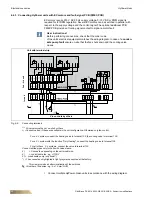
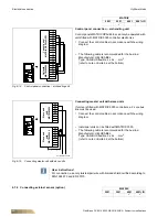
6.8.4 Line structure
The illustration shows the setup of the MATRIX.Net with line structure. As an example
two groups, each consisting of a control panel and a Global Module, are networked. In
addition, power supply of the control panel via the controller (terminals 95/99) is shown.
Fig. 6-30: Set up of MATRIX.Net in line structure
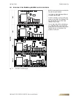
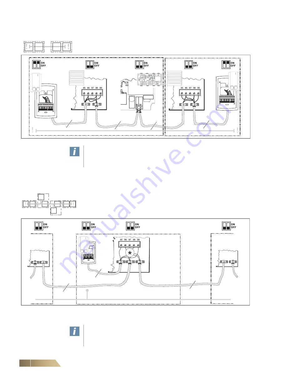
6.8.5 Line structure with branch feeder
The illustration shows the setup of the MATRIX.Net as line with branch feeder struc-
ture. A sample connection of a control panel via a branch feeder in multiple groups is
illustrated. The maximum allowed branch feeder length is 25 m.
Fig. 6-31: Structure of a MATRIX.Net in line structure with a branch feeder
* Since it is not permissible to connect three lines, an intermediate terminal must be provided! To do this, the intermediate
terminals (STV) mounted on the board (if not already occupied) or terminals fitted on site by others can be used
1
2
User instructions!
The data transfer cable must be run as demonstrated in fig. 6-30 so that only one
side of the respective shielding is applied – see “Shielding / Earthing” on page 75
Group 1
Group 2
4-wire
4-wire
2-wire
2-wire
1
2
3
X
2-wire
2-wire
4-wire
Group 1
Group 2
Group X
User instructions!
The data transfer cable must be run as demonstrated in fig. 6-30 so that only one
side of the respective shielding is applied – see “Shielding / Earthing” on page 75
Содержание HYPOWER-GEKO
Страница 1: ...HYPOWER GEKO OPERATION MANUAL ...