15
assembled with the same methods).
3.
Attach the push arm handle (#51) to the push arm (right) (#11) with 1 hexagonal bolt M10×25
(#65) and 1 arc pad Ø10 (#85); then lock the long pull handle (with iron piece) (#50) to the
other end of the push arm handle (#51) with 1 hexagonal bolt M10×25 (#65) and 1 large flat pad
Ø10 (#59).
4.
Assemble the left part in the same manner.
Installation steps
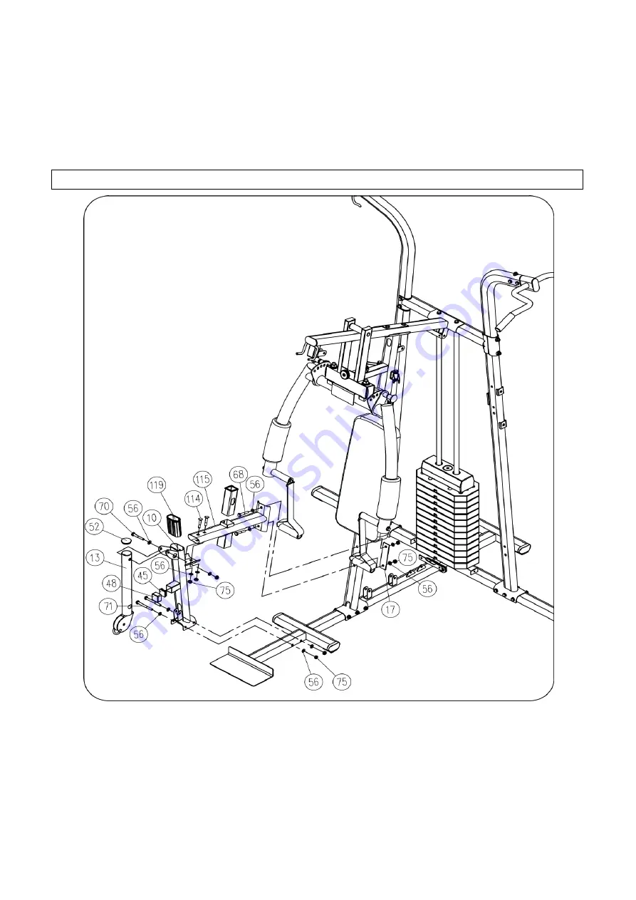
Figure 6
1.
Install 50x50 square bushings (#53) into cushion mounting rack (#115).
2.
Attach the saddle mounting rack (#115) and connecting piece (#17) to the front column (#4)
with 2 hex head bolts M10x60 (#68), 4 flat washers
Φ10
(#56) and 2 lock nuts M10 (#75).
3.
Attach a 40x80 elliptical bushing (#119) to saddle mount front support (#10); then attach 38x38
square pipe plug (#45) to saddle mount front support (#10) and sleeve 38x38 square pipe;
4.
Connect the front support of the saddle mount (#10) to the saddle mount (#115) with 2 M10x55
square well bolts (#114), 2 flat pads
Φ10
(#56) and 2 lock nuts M10 (#75).
5.
Then attach the front support (#10) to the front bottom support (#2) with 2 hex head bolts
Содержание MLD-M6
Страница 1: ... MLD M6 Fitness Equipment Co LTD ...
Страница 4: ...3 General Assembly Drawing MLD M6 Executed Standard GB17498 1 No Name Qty No Name Qty ...
Страница 7: ...6 108 40x100 elliptical flat pipe plug 2 ...
Страница 8: ...7 ...
Страница 9: ...8 ...
Страница 10: ...9 ...
Страница 30: ...29 ...


