


F1300N Rotary Table Operating Manual
Section 2: Setup
Rev A, February 2018
© 2017 Fisnar Inc. l Website:
www.fisnar.com
l E-mail:
15
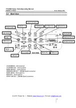
3.1 Drive cyclinder Setup
To correctly set up the drive cylinder for application usage:
After plumbing in the mains air supply to the 8mm fitting on the back of the rotary table,
and the 4mm cylinder in and clyinder out pipes into the correct flow relugator fittings.
Use and dummy program to set up the cylinder movement speeds
Fully close both flow regulators before beginning.
Start the Dummy program to actuate the pneumatics and being to move the drive
cylinder.
Slowly open the “Cylinder In” flow regulator to release the air pressure in the drive
cylinder and begin the movement down towards the dispesne location
When the cylionder is moving at a speed appropriate for the application use the locking
nut to set the flow regulator parameter.
After the Cylinder in flow regulator is set, then repeat the above to set the “Cylinder
Out” flow regulator the same way, by opening until the required speed is set and lock it
in place
The flow regulators are pneumatic dampeners, meaning they act as slow air release air
cushions to control the movement speed of the drive cylinder.
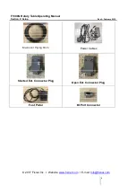
Cylinder out flow regulator,
showing locking nut and adjustable
knob for flow rate.


