


F1300N Rotary Table Operating Manual
Section 2: Setup
Rev A, February 2018
© 2017 Fisnar Inc. l Website:
www.fisnar.com
l E-mail:
14
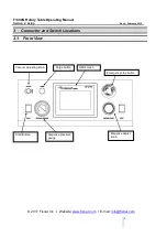
3.4.
When the Rotary table base is set on a secure work table, take the X axis mounting
post and fix it to the mounting table top, use the M5 x 25 cap head screws supplied
with the post.
3.5.
Mount the secondary Y axis post to the X axis post at an appropriate height for the
application. The post’s height is locked in place using the threaded locking handle and
slotted mounting bracket.
3.6.
Mount the air cylinder Z axis moving plate onto the Y axis mounting post, the mounting
bracket will slide on the post into position based on the application specified. The air
cylinder’s Y axis position and dispense angle can be locked in place using the
threaded locking handle. The “cylinder in” must be at the bottom of the drive cylinder or
the Z axis will travel in the wrong direction.
3.7.
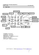
Connect the pneumatic pipes to the matching labelled tube to tube fittings. I.e. pipe
labelled “cylinder out” to back panel 4mm push connector labelled “cylinder out”.
Connect the cylinder in pipe to the cylinder in 4mm push connector. The Z axis drive
cylinder sensors connector to the back panel 4 pin connector labelled “sensor”
3.8.
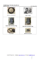
Connect the extras from the accessary box. Pneumatic plug into mains air out. Shorted
ext. connector to link the emergency stop signal. Mains air in, 6mm air fitting. Connect
the power plug to a 230vac mains power plug.
3.9.
Check all connections are secure, and none of the pneumatic connections are leaking
air.
3.10. Tie back all cables and air lines so that they will not interfere with the rotary tables
motion when the rotary table is operating. Be sure that the cables and air lines do not
restrict the motion of the rotary tables, Z axis drive cylinder and of the rotary tables
motor and make sure that they cannot become jammed as the rotary table moves in
the work area.
3.11. The mounting posts can but moved and slid into place and aligned with the area of
dispense of the specified part.
3.12. It is recommended to setup the flow control valves that regulate the drive cylinder
before positioning the dispense tip to the application. This can be done when driving the
cylinder in the “test screen”. Set the flow control to drive the cylinder at a controlled speed
that meets application requirements.
Note that this unit ships with a Shorted External Control Connector. This is not
connected when shipped. Unless this is plugged in, the unit will display an EMG
ERROR (Emergency Stop). Please insert the Shorted Connector.


