Lit. No. 49591, Rev. 05
9
July 15, 2020
27775, 28069, 57000, 57000‑1, 57000‑3
FINAL ADJUSTMENTS
Lift Chain
1.
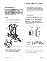
With the snowplow attached to a properly
ballasted vehicle and the blade lowered to the
ground, the A‑frame should be parallel with the
ground. If not, reposition the A‑frame using the
upper or lower A‑frame assembly holes.
2.
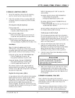
Adjust the length of the lift chain so that the
A‑frame hits the lower portion of the headgear
when the lift ram is fully extended (6").
WARNING
Keep 8' clear of the blade when it is being
raised, lowered, or angled. Do not stand
between vehicle and blade or directly in front
of the blade. If the blade hits or drops on you,
you could be seriously injured.
6"
Shown with blade raised.
3.
Remove and retain the U‑bolt and locknuts
securing the lift chain on the passenger's side of
the A‑frame. Reposition the U‑bolt in the chain so
that the chain is the same length as the chain on
the driver's side.
4.
Reattach the loose end of the lift chain to the
passenger's side of the A‑frame with the retained
U‑bolt and locknuts. The chain must be the same
length on both sides.
5.
Fully tighten the U‑bolts before lifting the blade.
Connecting Link and Lift Chain Spring
When the blade is lowered, the lift chain spring
provides slack in the lift chain for ease of mounting
and dismounting the blade.
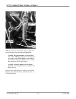
Your snowplow application may use either a lap link or
a quick link to connect the lift chain and spring.
The lift chain spring is installed at the factory in the lift
chain link indicated in the chart below.
Snowplow
Number of Links
from Driver‑Side U‑Bolt
Lap Link
Quick Link
SD Series
8
9
However, due to variations in vehicle frame height,
it may be necessary to adjust the spring location to
ensure optimal performance.
If you encounter mounting or dismounting difficulty, the
attachment point of the connecting link and spring can
be changed to a link on the lift chain that will add or
remove slack from the lift chain.
Lap Link
Quick Link


