


840653
36
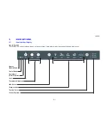
8.1.13
Reed Switch
The reed switch is located on the back wall and in line with the right hand drawer slide, which contains a
magnet. The reed switch is encapsulated within a plastic housing, which is clipped under the plastic covers
on the back wall.
It is used to provide feedback to the power/control module to activate the evaporator fan and to turn off the
interior light when the drawer is closed.
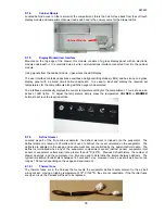
8.1.14
Thermistor Temperature Sensors
These sensors are used to monitor temperatures within the CoolDrawer and provide feedback to the
power/control module. There are five sensors:
1. The defrost sensor is used, along with the evaporator inlet sensor and the evaporator outlet sensor, to
measure the temperature at the evaporator when in defrost.
2. The evaporator inlet sensor mounted on the evaporator coil inlet is used to measure the coil inlet
temperature.
3. The evaporator outlet sensor mounted on the evaporator coil outlet is used to measure the coil outlet
temperature.
4. The compartment temperature sensor. This sensor is located on the back wall and in the centre of the
compartment at the top. It senses the cold air movement from the evaporator within the compartment.
5. The filter drier sensor. This is used to measure the temperature of the refrigerant entering the filter
drier. This information is used to control the backpressure and the speeds of the compressor at certain
ambients in which the VC compressor may be running. It is important that good thermal contact is made
with the sensor surface to the filter drier.
Thermistor sensors are used for temperature measurement. Their electrical resistance changes as the
temperature changes. The table below lists some typical resistance values. The temperature can be read
using Diagnostic Mode as described in Section 10.1.3.
THERMISTOR SENSOR RESISTANCE TABLE
TEMPERATURE (
°
C)
RESISTANCE
(K Ohms
±
5%)
-30.0
25.17
-25.0
19.43
-20.0
15.13
-15.0
11.88
-10.0
9.392
-5.0 7.481
0.0 6.000
5.0 4.844
10.0 3.935
15.0 3.217
20.0 2.644
25.0 2.186
30.0 1.817
35.0 1.518
40.0 1.274
45.0 1.075
50.0 0.911
Содержание RB36S25MKIW
Страница 1: ...840653 Service Manual CoolDrawer Models RB36S25MKIW RB90S64MKIW ...
Страница 12: ...840653 12 3 4 Integrated Panel Preparation ...
Страница 14: ...840653 14 3 5 Create Cut Outs In Frame 3 6 Locate And Secure Install Brackets ...
Страница 15: ...840653 15 3 7 Attach Inlet And Outlet Vent Ducts 3 8 Attach Power Cord And Trim Brackets ...
Страница 16: ...840653 16 3 9 Move Product Into Cavity 3 10 Fit Drawer Panel Attachment Hooks ...
Страница 17: ...840653 17 3 11 Attach Drawer Panel To Front Of Drawer ...
Страница 18: ...840653 18 3 12 Secure Trim Brackets To Cabinetry 3 13 Attach Trims To Sides Of Cabinetry ...
Страница 19: ...840653 19 3 14 Attach False Panel 3 15 Check Operation ...
Страница 53: ...840653 53 11 WIRING DIAGRAMS Ω Ω Ω Ω Ω Ω Ω Ω Ω Ω ...
Страница 54: ...840653 54 ...
Страница 77: ...840653 77 ...


