


840653
35
8.1.10
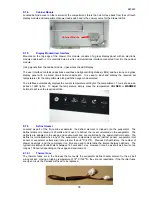
Interior LED Lights
These are used to illuminate the interior of the drawer when it is opened, and are located on the back face of
the drawer front. They consist of three LEDs mounted on a printed circuit board and connected to the wiring
harness by means of a plug. Individual LEDs are not replaceable as they all part of the PCB they are
mounted on.
8.1.11
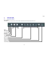
Speaker
This is located on the end of the display module and is used as sound recognition between the user and the
capacitive touch switches that make up the user interface.
8.1.12
Wiring Harness Air Bell
Located in the evaporator sump of the cabinet, this is the plug termination area for the defrost element,
evaporator fan motor, sensors and auxiliary heater. The air bell cover prevents water from entering the
plugs and sockets that are all terminated at this point. The cover must always be fitted, taking care not to
pinch the harness wires.
Wiring Harness Air Bell Cover
Содержание RB36S25MKIW
Страница 1: ...840653 Service Manual CoolDrawer Models RB36S25MKIW RB90S64MKIW ...
Страница 12: ...840653 12 3 4 Integrated Panel Preparation ...
Страница 14: ...840653 14 3 5 Create Cut Outs In Frame 3 6 Locate And Secure Install Brackets ...
Страница 15: ...840653 15 3 7 Attach Inlet And Outlet Vent Ducts 3 8 Attach Power Cord And Trim Brackets ...
Страница 16: ...840653 16 3 9 Move Product Into Cavity 3 10 Fit Drawer Panel Attachment Hooks ...
Страница 17: ...840653 17 3 11 Attach Drawer Panel To Front Of Drawer ...
Страница 18: ...840653 18 3 12 Secure Trim Brackets To Cabinetry 3 13 Attach Trims To Sides Of Cabinetry ...
Страница 19: ...840653 19 3 14 Attach False Panel 3 15 Check Operation ...
Страница 53: ...840653 53 11 WIRING DIAGRAMS Ω Ω Ω Ω Ω Ω Ω Ω Ω Ω ...
Страница 54: ...840653 54 ...
Страница 77: ...840653 77 ...


