10
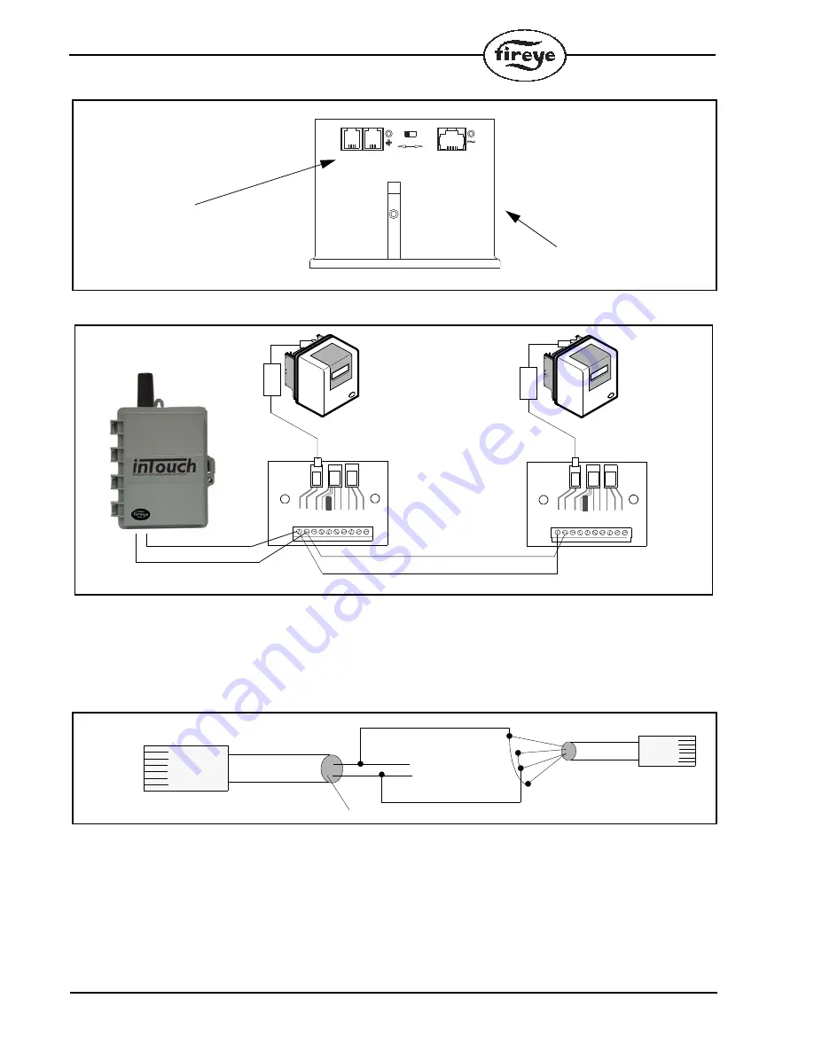
FIGURE 5.
BURNERLOGIX CONNECTORS
FIGURE 6.
WIRING FOR MODBUS PROTOCOL
Alternate Hook-up Method
To connect the inTouch to a Flame-Monitor or BurnerLogix without the use of the ED610, connect
the supplied cable from the inTouch to the ED512 directly or to a telephone handset type cable that is
commercially available.
FIGURE 7.
Verifying Communication
After all Fireye controls are properly connected and individually addressed, their connection to the
inTouch device can be verified by depressing and releasing the OPTION button 3 times. The 7-seg-
ment LED display will switch to a dash (—) symbol followed by the addresses of the devices it is
successfully communicating. The display will then show the dash symbol followed by the signal
strength power level it is receiving.
%1//5
%1//5
':2
':2
470%*-
470%*-
YB110 or ZB110
RJ12 CONNECTORS
FOR ED512 CABLE
ED610
10 9 8 7 6 5 4 3 2 1
J5
J1
ED610
10 9 8 7 6 5 4 3 2 1
J5
J1
E110
ED512-2, -4, -8
FLAME-MONITOR
BELDEN 8761
E110
ED512-2, -4, -8
FLAME-MONITOR
CLEAR
BLACK
TO RJ12 CONNECTOR ON
EP/EPD PROGRAMMER
TO RJ12 CONNECTOR ON
EP/EPD PROGRAMMER
J2
J2
FERRITE
CORE
FERRITE
CORE
BLACK (A)
YELLOW (B)
SHOWN
SHOWN
GREEN (NOT USED)
INTOUCH CABLE
ED512
(CUT OFF OND END)
BLACK (A)
YELLOW (B)
BLACK
RED
GREE
N
YE
LL
OW


