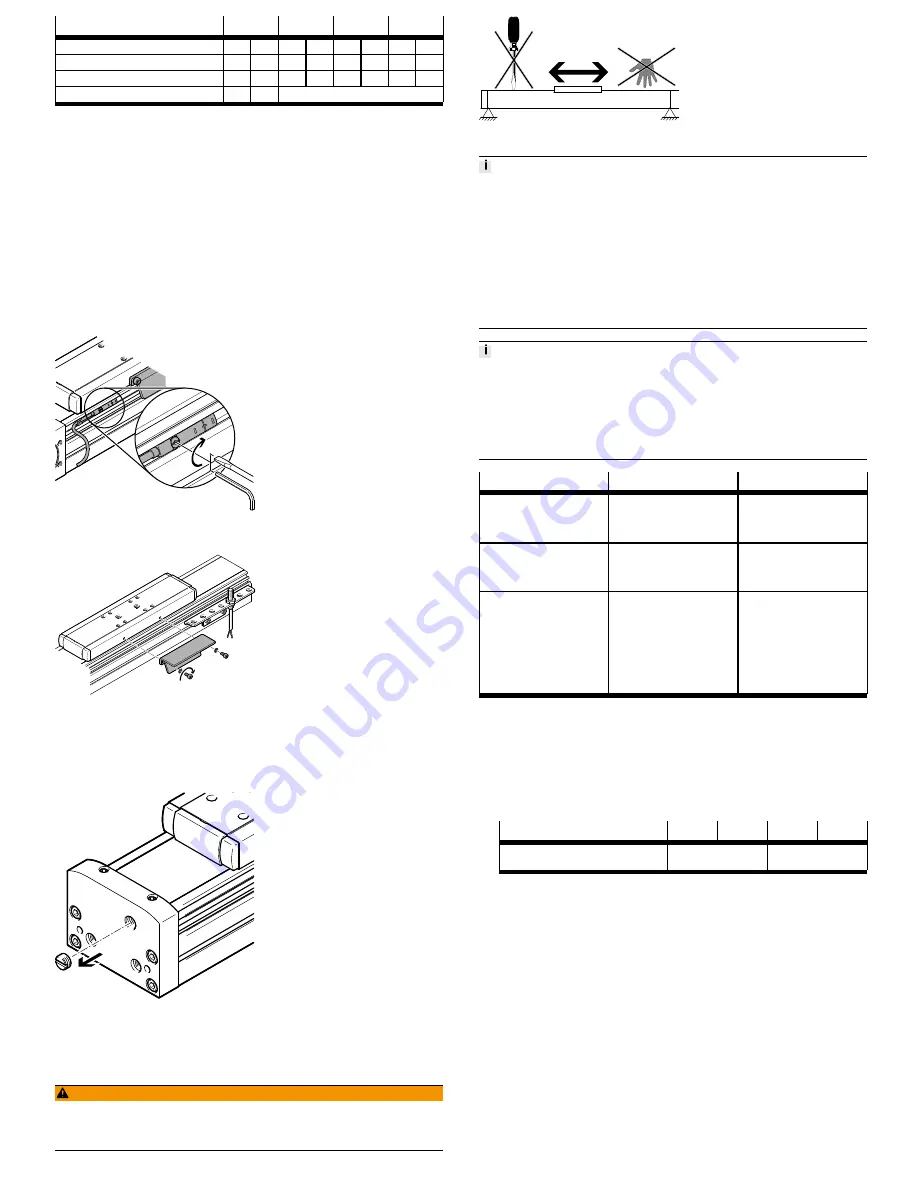
Size
70
80
120
150
Screw
M5
M6
M5
M6
M5
M6
M6
M8
Max. screw-in depth D
[mm]
7.5
9.5
12.5
14
Tightening torque
[Nm]
6
10
6
10
6
10
10
24
Centring H7
[mm]
Æ
5
Æ
9
Æ
9
Tab. 4 Mounting the payload
Mounting accessories
To protect the end positions against uncontrolled excess travel:
•
Check whether proximity sensors are necessary (as safety limit switches or
hardware limit switches).
If proximity sensors are used as limit switches:
•
Preferably use proximity sensors with normally-closed function. These will
protect a spindle axis against excess travel of the end position in case of a
broken proximity sensor cable.
If proximity sensors are used as reference switches:
•
Use proximity sensors that correspond to the input of the controller being
used.
•
Use proximity sensors with switch lug. Assembly instructions
è
www.festo.com/sp.
Mounting options for proximity sensors
Fig. 11 In the slots
Fig. 12 With sensor bracket
•
Avoid external influence caused by magnetic or ferritic parts in the vicinity of
the proximity sensors. Distance to slot nuts: ≥ 10 mm.
Avoid contamination:
•
Use slot covers in all unused slots
è
www.festo.com/catalogue.
Fig. 13 Remove threaded pin
•
Connect sealing air. To do this, remove the threaded pin on the cover and
connect compressed air/vacuum
è
Fig.13.
6
Commissioning
WARNING!
Danger of crushing as a result of moving loads
•
Do not reach into the path of the moving components.
•
Install the corresponding protective devices (e.g. protective grille).
Fig. 14 Unexpected movement of components.
Incorrect specification values for the braking ramp in STOP statuses (e.g. EMER-
GENCY OFF, Quick Stop) result in an overloading of the spindle axis and can des-
troy it or drastically reduce service life.
•
Check the settings for all braking ramps in the controller or the higher-order
control system (deceleration values and jerk).
•
Taking the travel speed, moveable load and mounting position into account,
set the delay values (brake delay and delay times) in such a way that the max-
imum drive torque or feed force of the spindle axis used is not exceeded.
•
Take the travel speed, moveable load and mounting position into account.
•
Use the Festo PositioningDrives design software to configure the spindle axis
è
www.festo.com.
Block-shaped acceleration profiles (without jerk limitation) cause high peaks in
the drive force that can lead to an overloading of the drive. Due to overshooting
effects, positions outside of the permissible range may also occur. A jerk-limited
acceleration specification reduces vibrations in the entire system and has a posit-
ive effect on stress in the mechanical system.
•
Check adjustments to the controller settings (e.g. jerk limitation, smoothing
of the acceleration profile).
Procedure
Purpose
Note
Travel check
Determining the approach dir-
ection of the motor
Even with identical control,
motors of the same design can
turn in opposite directions due
to different wiring.
Homing to reference switch
Comparison of real situation to
the image of the controller
The homing run may only be
performed towards the refer-
ence switch
è
www.festo.com/sp.
Test run
Checking the overall behaviour
Check the requirements:
–
The slide moves through
the intended positioning
cycle completely.
–
Slide stops as soon as a
limit switch is reached.
After a successful test run, the
spindle axis is ready for opera-
tion.
Tab. 5 Commissioning
7
Maintenance
Check wear:
•
Check reversing backlash (reverse play) of the slide for wear of the spindle
nut during each maintenance procedure. The wear on the ball screw will lead
to increased noise in the long term and eventually cause the ball screw drive
to block or the spindle nut to break.
Size
70
80
120
150
Maximum permissible revers-
ing backlash
[mm]
0.1
0.2
Tab. 6 Maximum permissible reversing backlash
Checking the cover strip:
–
Check the cover strip after every 2000 km of operating distance. Waves on
the cover strip are a sign of wear on the belt reversal device.
–
Whenever waves form, retighten cover strip on both sides:
1. Loosen the screws
è
Fig.15,
5
.
2. Push the cover strip into the cover.
3. Tighten cover strip with a clamping element
è
Fig.15,
6
.
4. Tighten the screws. Tightening torque: 2 Nm.
If the cover strip can no longer be retensioned:
•
Replace belt reversal devices
è
www.festo.com/spareparts.
Lubricating the spindle and guide:


