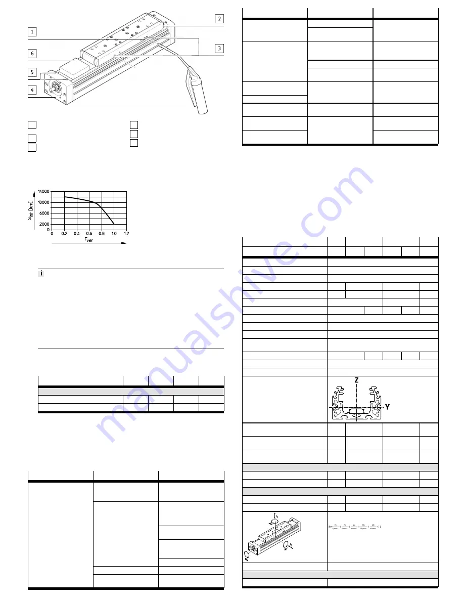
1 Relubrication opening of the ball
screw
2 Cover strip
3 Relubrication openings of the
guide
4 Cover
5 Screws
6 Clamping element
Fig. 15 Lubricating the ball screw and guide
1. Calculate load comparison factor f
v
with the help of the formula for combined
loads
è
9 Technical data: mechanical.
Fig. 16 Lubrication interval
2. Read off lubrication interval S
int
è
Fig.16.
The lubrication interval S
int
is dependent on the load acting on the product.
Load factors:
•
Dusty and dirty environment
•
Nominal stroke
>
2000 mm or
<
300 mm
•
Travel profile
Z
triangular operation (frequent acceleration and braking)
•
Ambient temperature
>
+ 40 °C
•
Age of the product
>
3 years
If one of these factors applies, halve the lubrication interval S
int
.
If several factors apply at the same time, reduce the lubrication interval S
int
by
three-quarters.
3. Lubricate the guide and ball screw at all relubrication openings
è
Fig.15.
Accessories and permitted lubricants
è
3.1 Not included in the delivery.
Amount of lubricant at each relubrication opening:
Size
70
80
120
150
Amount of lubricant
Ball screw
[g]
2
2.5
3
15
Guide
[g]
0.4
0.8
2.0
3.4
Tab. 7 Amount of lubricant
7.1
Cleaning and maintenance
•
Clean the spindle axis with a soft cloth as required. Cleaning agents include
all non-abrasive media.
8
Malfunctions
8.1
Fault clearance
Malfunction
Possible cause
Remedy
Coupling distance incorrect
Observe the permissible coup-
ling spacings
è
www.festo.com/sp.
Install the axis so it is free of
tension; maintain evenness of
the bearing surface
è
5.1 Mechanical installation.
Change arrangement of the
tool/payload.
Align the spindle axis so that it
is exactly parallel to the second
spindle axis.
Tensions
Change the travel speed
Controller is incorrectly set
Changing the parameters
Squeaking noises, vibrations or
the axis is not running
smoothly.
Insufficient lubrication at guide. Lubricate the spindle axis
è
7 Maintenance.
Malfunction
Possible cause
Remedy
Guide defective
Squeaking noises, vibrations or
the axis is not running
smoothly.
Guide or cover strip reversal
devices worn
Send spindle axis to Festo or
contact the local Festo service.
Coupling spins.
Check the assembly of the
motor mounting kit
è
www.festo.com/sp.
Load levels are too high.
Reduce load mass/torques.
Slide does not move.
Retaining screws on tool are
too long.
Observe the maximum screw-in
depth
è
Mounting attachments
The reversing backlash is too
large
è
7 Maintenance
The idling torque increases.
Wear
Return spindle axis to Festo for
repair
è
8.2 Repair.
Slide travels over end position.
Proximity sensors do not oper-
ate
Check proximity sensor, con-
nections and controller.
Cover strip has waves.
Retension cover strip
è
7 Maintenance
Aluminium wear on spindle
axis.
Wear on belt reversal device.
Replace the belt reversal device
è
www.festo.com/spareparts.
Tab. 8 Fault clearance
8.2
Repair
•
Remove motor cables and mounting components.
If repairs are required:
–
Send the spindle axis to the Festo repair service.
–
Information about spare parts and accessories
è
www.festo.com/spareparts.
8.3
Disposal
Dispose of the packaging and the axis at the end of its useful life through environ-
mentally friendly recycling in accordance with applicable specifications.
9
Technical data: mechanical
Size
1)
70
80
120
150
Spindle pitch
10
10
20
10
25
40
Design
Electromechanical axis with ball screw
Guide
Recirculating ball bearing guide
Mounting position
Any
Max. feed force F
v
[N]
650
1600
3400
6400
Max. no-load driving torque
2)
[Nm]
0.45
0.75
2.25
6.5
Maximum speed
[1/min]
3000
3600
3000
Max. speed
[m/s]
0.5
1
0.6
1.5
2
Max. acceleration
[m/s
2
]
15
Repetition accuracy
[mm]
± 0.02
Reversing backlash (new)
[mm]
<
0.01
Reversing backlash (limit
value)
è
7 Maintenance
Feed constant
[mm/U]
10
20
10
25
40
Ambient temperature
[°C]
–10 … +60
Degree of protection
IP40
2nd degree of surface torque
l
y
[mm
4
]
165 x -
10
3
310 x 10
3
1.24 x 10
6
4.70 x-
10
6
l
z
[mm
4
]
472 x -
10
3
977 x 10
3
3.80 x 10
6
11.81 -
x 10
6
Max. radial force on drive
shaft
[N]
220
250
500
4000
Maximum permissible forces on the slide
F
y
[N]
1500
2500
5500
5500
F
z
[N]
1850
3050
6890
11000
Maximum permissible torques on the slide
M
x
[Nm]
16
36
104
167
M
y
= M
z
[Nm]
132
228
680
1150
Determination of the load compensation factor for com-
bined loads:
Information on materials
Contains paint-wetting impairment substances
Materials
Cover, profile, slide
Anodised aluminium


