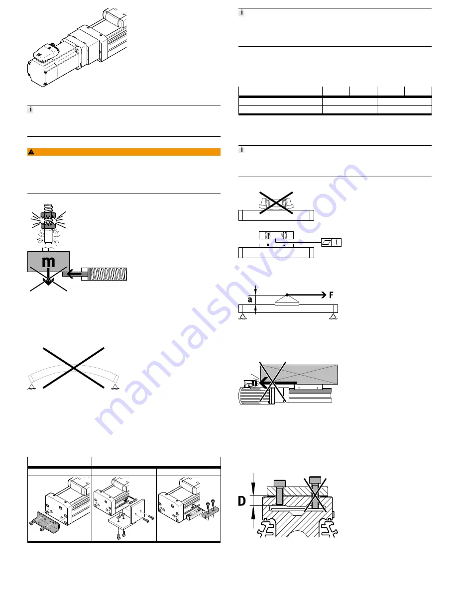
Fig. 4 Motor assembly
The reference position is lost when the motor is dismounted (e.g., when turning
the motor around).
•
Start homing
è
6 Commissioning.
Mounting position vertical or diagonal:
WARNING!
Risk of injury due to falling working loads.
In a power failure or if the spindle nut breaks, the working load may fall.
•
Only use motors with integrated spring-loaded holding brakes.
•
Implement external safety precautions to prevent the spindle nut from break-
ing (e.g. tooth clinking, moveable bolts or emergency buffers).
Fig. 5 Working load
Assembling the spindle axis
Prerequisites:
•
Position the spindle axis in such a way that its operating elements are access-
ible (e.g. relubrication openings).
•
Install spindle axis without tension or distortion.
Fig. 6 Assembly surface flatness
•
Fasten spindle axis to a mounting surface with flatness of 0.05% of the stroke
length, but max. 0.5mm. For gantry applications, attention must also be paid
to parallel alignment or product heights in alignment of the axes. For addi-
tional information, contact your local Festo Service
è
www.festo.com.
•
Take the required support clearances into consideration
è
9 Technical data: mechanical.
Interfaces for mounting components
On the cover
On the profile
e.g. with foot mounting HPE
e.g. with slot nuts NST
e.g. with profile mounting MUE
Tab. 2 Interfaces for mounting components
Danger of screws being pulled out if the spindle axis is only mounted to the cov-
ers and the torque load around the longitudinal axis is too great.
•
If there is high loading, mount the spindle axis on the profile with additional
mounting components.
1. Select mounting components
è
www.festo.com/catalogue.
2. Mount the mounting components outside the positioning range (avoid colli-
sions).
3. Mount the spindle axis.
4. Tighten the retaining screws evenly.
Size
70
80
120
150
Screw (cover)
M5
M8
Tightening torque
[Nm]
6
24
Tab. 3 Tightening torques of the retaining screws
Mounting attachments
Requirements
An uneven attachment component bends the slide and shortens the service life of
the guide.
•
Use an attachment component with an even surface. Evenness: t = 0.01 mm
Fig. 7 Evenness of payload
Fig. 8 Position the payload
•
Set down nominal load in such a way that the tilt moment resulting from force
F (parallel to the axis of movement) and lever arm are kept as small as pos-
sible
è
Fig.8.
Fig. 9 Protruding payload
•
Avoid collisions of the mounting part and payload with other mounting parts
è
Fig.9.
For attachment components with their own guide:
•
Adjust the guide and axis so that they are exactly parallel or use a connection
that permits tolerance compensation. This will prevent overloading of the
guide.
Mounting:
Fig. 10 Max. screw-in depth
•
Fasten the attachment to the slide with screws and centring sleeves. Observe
the maximum screw-in depth D and tightening torque
è
Tab. 4 Mounting the payload.


