


6
Commissioning
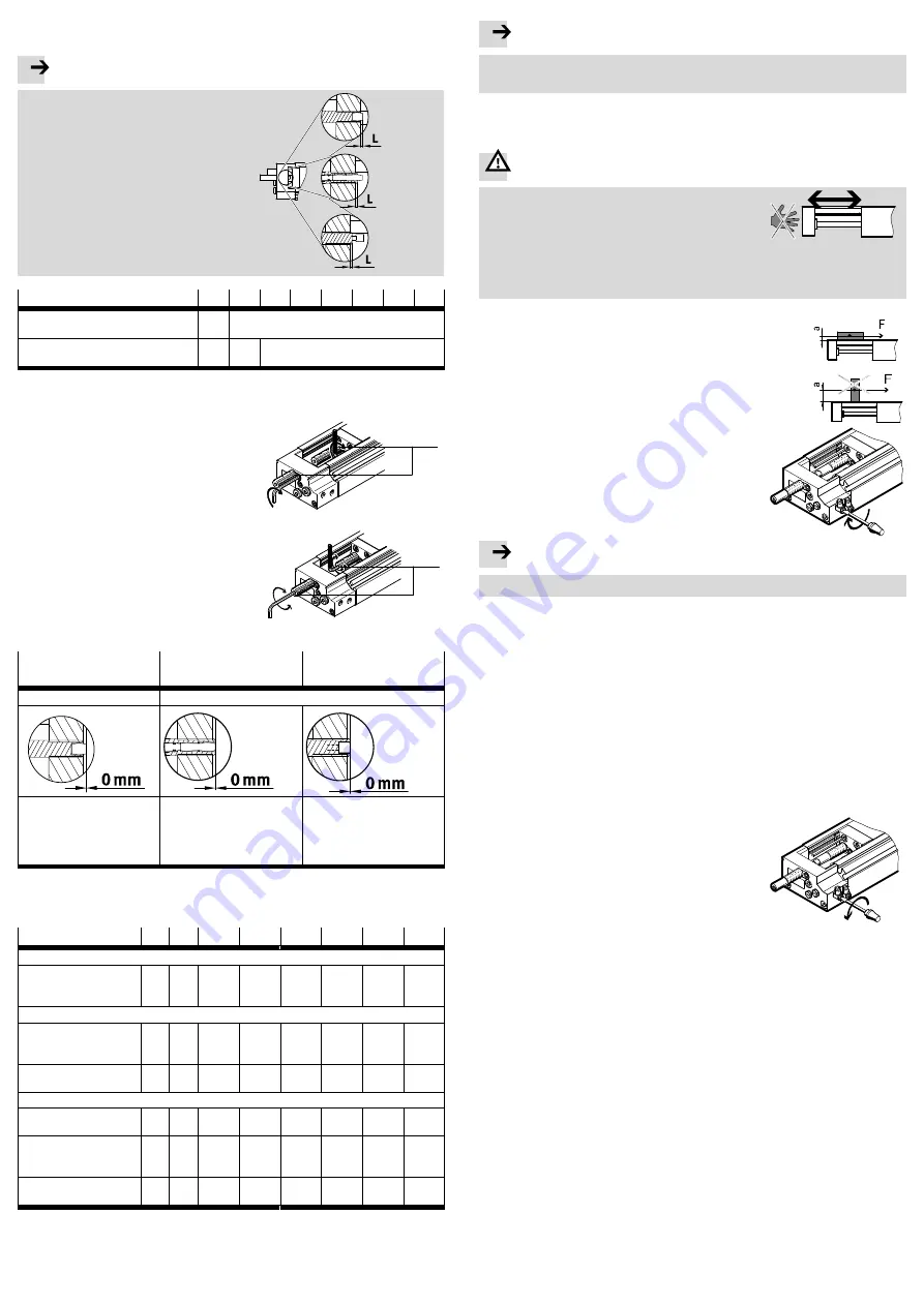
6.1 Preparing for commissioning
Note
Make sure that the following conditions
are observed:
– The distance L of the cushioning com
ponent must be maintained at a min
imum (factory setting)
(
è
Falling below the factory settings
destroys the guide.
– For all setting work, all threads of the
cushioning component are constantly
being manipulated.
Fig. 16
DGSL-…-E
DGSL-…-P
DGSL-…-P1
DGSL-…-Y3
DGSL-…-Y11
DGSL
4
6
8
10
12
16
20
25
Distance L with
DGSL-…-E/-P/-P1
[mm]
1
1.5
Distance L with
DGSL-…-Y3/-Y11
[mm]
–
–
1.5
Fig. 17
For precision adjustment of the end positions:
1. Loosen clamping component
aE
.
2. Position the slide by hand in the desired
end position.
Fig. 18
aE
3. Turn the cushioning component
1
with a
hexagon wrench until the end position is
reached (
è
The max. torque must be observed thereby
(
è
4. Retighten the clamping component with
the following tightening torque (
è
Fig. 19
1
DGSL-…-E,DGSL-…-P
with rubber buffer
DGSL-…-P1 with rubber
buffer and stop sleeve
DGSL-…-Y3
,
DGSL-…-Y11
with shock absorber
1)
No metallic stop
Metallic stop
The rubber buffer touches the
slide.
The stop sleeve touches the
slide (against the force of the
cushioning)
The shock absorber housing/
reducing sleeve
(for DGSL-…-Y11) touches the
slide (against the force of the
shock absorber)
1)
If the max. torque for the internal hexagon socket at the DGSL-…-Y3
is fallen below, the hexagon in the
shock absorber spins. The max. torque is summarised in the following table (
è
Fig. 20
DGSL
4
6
8
10
12
16
20
25
For all DGSL
Tightening torque
clamping
component
[Nm]
0.15
0.2
0.3
0.8
1.2
2.5
2.5
3.5
Only for DGSL-…-Y3
Max. torque
internal hexagon
socket
[Nm]
–
–
0.5
0.8
2.2
5
8
13
Shock absorber
type DYSW-…-Y1F
–
–
4-6
5-8
7-10
8-14
10-17
12-20
Only for DGSL-…-Y11
Max. torque
reducing sleeve
[Nm]
–
–
–
0.8
2.2
5
8
13
Max. torque
internal hexagon
socket
[Nm]
–
–
–
0.5
0.8
2.2
5
8
Shock absorber
type DYSW-…-Y1F
–
–
–
4-6
5-8
7-10
8-14
10-17
Fig. 21
Note
The exact slide position must be checked during a test run with compressed air
applied and, if necessary, corrected.
6.2 Carrying out commissioning
Before each commissioning and in operation:
Warning
Make sure that in the travel range of the drive
– Nobody can reach into the path of the movable
components (e.g. by providing a protective
guard).
– There are no foreign objects (e.g. hexagon
wrench when setting the end position under pres
sure).
Fig. 22
Place your effective load on the slide of the
DGSL so that the break-down torque of the
dynamic force F and the lever arm a remains
small.
Fig. 23
Turn both upstream one-way flow control valves
– at first completely closed
– then one rotation open again
Fig. 24
Note
Make sure that the operating conditions lie within the permissible ranges.
1. Pressurize the drive as follows:
– Pressurize the drive by
slowly
pressurizing one side.
For slow start-up pressurisation, use start-up valve type HEL.
The slide moves into an end position.
2. Start a test run with the moveable mass.
3. During the test run check whether the following points need to be modified:
– the speed and the acceleration of the moveable mass
– the end position
– the mass of the effective load
– the position of the proximity sensors.
If this is the case, the modifications must be carried out only when the slide is at
rest.
4. Open up the one-way flow control valves slowly
until the desired slide speed is reached.
The maximum permissible speed must
not
be
exceeded here (
è
12 Technical data).
The slide should reach the end position safely, but
not strike hard against it.
Too hard of an impact will cause the slide to re
bound out of the end position.
Fig. 25
If the slide can be heard to strike hard:
5. Interrupt the test run.
Causes of hard knocking may be:
– the moveable mass is too high
– the slide speed is too high
– no compressed air cushion on the exhaust side
– cushioning not sufficient (can be set for DGSL-…
-P1
).
6. Make sure you remedy the above-mentioned causes.
7. Repeat the test run.
When all necessary corrections have been undertaken:
8. End the test run.
9. Fasten the proximity switches in their final positions.


