26
Festo — CPX-F8DE-P — 2022-10d
System overview CPX-F8DE-P
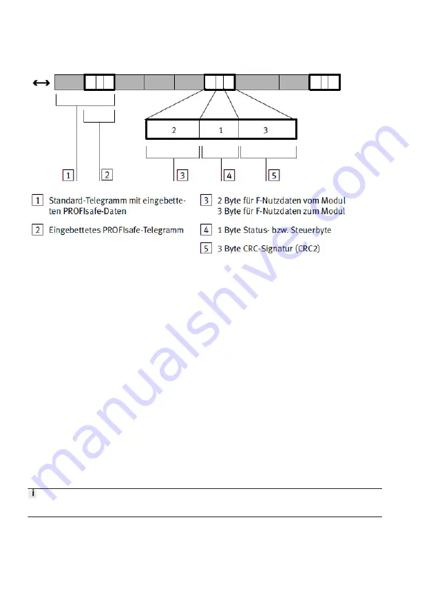
Fig. 3: Telegram structure of the input module CPX-F8DE-P
Data are transmitted on the same physical basis as the transfer of process data to a standard module.
There is a distinction between the type of data and the interpretation of the data by the F-Device
(PROFIsafe slave).
The following applies for PROFIsafe communication in connection with the input module CPX-F8DE-P:
–
the module supports the PROFIsafe bus profile V2.4 in the V2 mode
–
parameterisation to V1 mode is rejected.
2.2.2
Process image (I/O image)
The safety features of PROFIsafe mean that the input module CPX-F8DE-P occupies 7 bytes for outputs
and 6 bytes for inputs in the process image of the CPX terminal.
Outputs consist of:
–
3 bytes output data (F-user data,
Tab. 15 Bit pattern of the output data (F-user data, bytes 0, 1
–
1 control byte (for PROFIsafe communication)
–
3 bytes CRC (for PROFIsafe communication).
Inputs consist of:
–
2 bytes input data (F-user data,
Tab. 16 Bit pattern of the input data (F user data, bytes 0 and 1))
–
1 status byte (for PROFIsafe communication)
–
3 bytes CRC (for PROFIsafe communication).
Function modes are set via the output data from the input module.
2.2.3
Bit pattern of the output and input data (F-user data)
Output data
Byte 0 serves to activate channel-based passivation and to acknowledge channel errors


