background image

Designated use

The CP fieldbus node CP-FB9-E documented in this
manual is designated exclusively for use as a slave on
the PROFIBUS-DP. Festo CP modules can be con-
nected to the fieldbus node CP-FB9-E. The CP node
may only be used as follows:

– as designated

– in original condition

– without unauthorized modifications

– in faultless technical condition.

The specified limit values for pressures, temperatures,
electrical data, moments, etc. must be observed when
additional commercially-available components such as
sensors and actuators are connected. Please comply
also with national and local safety laws and regulations.

Target group

This manual is directed exclusively at technicians who
are trained in control and automation technology and
who have experience in installing, commissioning, pro-
gramming and diagnosing  PROFIBUS-DP slaves.

Contents and general safety instructions 

CP FB13-E  9904b

V

Содержание Compact Performance CP-FB9-E

Страница 1: ...Compact Performance CP fieldbus node 13 Programming and diagnosis fieldbus protocol PROFIBUS DP as per EN 50170 DIN 19245 ...

Страница 2: ...ibution and utilization of this docu ment as well as the communication of its contents to others without expressed authorization is prohibited Of fenders will be held liable for the payment of damages All rights reserved in particular the right to carry out patent utility model or ornamental design registration Printed on 100 recycled paper Contents and general safety instructions CP FB13 E 9904b ...

Страница 3: ...Order no 165 213 Title Manual Designation P BE CP FB13 E GB Contents and general safety instructions II CP FB13 E 9904b ...

Страница 4: ...S DP interface 1 14 1 6 1 Connecting the screening 1 15 1 6 2 Bus termination with terminating resistors 1 16 1 6 3 Optical fibre waveguide connection 1 18 2 Commissioning 2 1 Preparing the CP system for operation on the PROFIBUS DP 2 3 2 1 1 Operating voltage 2 3 2 1 2 Saving the string assignment 2 3 2 1 3 Compiling the configuration list 2 5 2 1 4 General 2 6 2 2 Configuration with a Siemens ma...

Страница 5: ...the bus node 3 3 3 1 1 Normal operating status 3 4 3 1 2 Diagnosis operating voltage POWER or POWER V 3 5 3 1 3 Diagnosis LED BUS ERROR 3 6 3 2 Testing the valves 3 7 3 3 Diagnosis via PROFIBUS DP 3 9 3 3 1 Diagnostic words 3 9 3 3 2 Diagnostic information 3 12 3 4 Error treatment 3 17 3 4 1 General DP master 3 18 3 4 2 Siemens SIMATIC S5 S7 3 18 3 5 STEP 7 V4 x Online diagnosis via diagnostic buf...

Страница 6: ...ion The specified limit values for pressures temperatures electrical data moments etc must be observed when additional commercially available components such as sensors and actuators are connected Please comply also with national and local safety laws and regulations Target group This manual is directed exclusively at technicians who are trained in control and automation technology and who have ex...

Страница 7: ...e 13 for PROFIBUS DP as per EN 50170 DIN 19245 Enclosed with this manual is a CD ROM with device master files Information on the contents can be found in the file readme Information on further CP modules can be found in the relevant manual This is summarized in a table further in this chapter Contents and general safety instructions VI CP FB13 E 9904b ...

Страница 8: ...ed by pictograms Danger categories A distinction is made between the following WARNING This means that personal injury or damage to property may occur if these instructions are not observed CAUTION This means that damage to property may occur if these instructions are not observed PLEASE NOTE This means that this instruction must also be observed Contents and general safety instructions CP FB13 E ...

Страница 9: ...voltage or undefined voltage states of the electronic components which can affect connected cir cutis Electrostatically vulnerable components These will be damaged if you touch the contact surfaces This mark indicates activities which can be carried out in any order Text markings 1 Figures indicate activities which must be carried out in the numerical order of the figures Hyphens indicate general ...

Страница 10: ...neumatics CP modules electronics Contents Special information on commissioning programming and diagnosing related to the node used Information on fitting installing and com missioning CPA or CPV valve terminals Information on fitting installing and commissioning CP I O modules Fig 0 1 Manuals on the CP system AA AA AA AA AA AA AAAA AAAA AAAA AAAA A A A A AA AA AA AA AA AA AA AA AA AA AA A A A AA A...

Страница 11: ...ovide digital inputs and outputs CP input and CP output modules I Os Digital inputs and outputs Node CP fieldbus node with without fieldbus connection to which the I O modules are connected Octet Number of address words reserved by the CP system O Digital output PLC IPC Programmable logic controller industrial PC Save SAVE buttons Save the current string assignment connected I Os when the CP syste...

Страница 12: ...Chapter 1 Installation 1 Installation CP FB13 E 9904b 1 1 ...

Страница 13: ...te and fieldbus length 1 9 1 3 1 Branch line lenght 1 10 1 4 Connecting CP modules 1 11 1 5 Connecting the operating voltage 1 12 1 6 Connecting the PROFIBUS DP interface 1 13 1 6 1 Connecting the screening 1 14 1 6 2 Bus termination with terminating resistors 1 15 1 6 3 Optical fibre waveguide connection 1 17 1 Installation 1 2 CP FB13 E 9904b ...

Страница 14: ... the connected actuators undefined switching states of the electronic components CAUTION The node of the CP system contains electrostatically vulnerable components Do not therefore touch any components Please observe the regulations for dealing with electrostatically vulnerable components In this way you will avoid irreparable damage to the electronic components on the node General information on ...

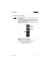
Страница 15: ...e cover by lifting it up To close the cover replace it and tighten the screws again by hand PLEASE NOTE Tighten the screws of the switch cover only by hand WARNING Before commissioning Make sure that switch elements 3 6 are set at PROFIBUS DP During operation Do not modify the setting of the DIL switches In this way you can avoid unintentional reactions of the connected actuators 1 Installation 1 ...

Страница 16: ...1 2 DIL switch Cover screws Fig 1 1 Position of the DIL switch 2 1 1 Installation CP FB13 E 9904b 1 5 ...

Страница 17: ...t DIL switch factory setting Switch element Function description 1 fieldbus address ON fieldbus address 100 OFF fieldbus address 100 2 Diagnostic information VValves VOutputs ON active OFF not active 3 Fieldbus protocol PROFIBUS DP ON must be set at ON OFF reserved 4 Fieldbus protocol ON must be set at ON OFF reserved 5 Fieldbus protocol ON must be set at ON OFF reserved 6 Fieldbus protocol ON res...

Страница 18: ... be addressed by the fieldbus addresses set on the address selector switches 1 2 3 Address selector switch UNITS figure Address selector switch TENS figure Address selector switch HUNDREDS figure Fig 1 2 Setting the fieldbus address on the address selector switches 6 5 2 7 8 9 0 1 3 4 6 5 2 7 8 9 0 1 3 4 1 2 3 1 Installation CP FB13 E 9904b 1 7 ...

Страница 19: ...s set Summary of possible fieldbus addresses PLEASE NOTE Fieldbus addresses may only be assigned once per PROFIBUS DP interface Observe also any restrictions concerning the assignment of fieldbus addresses by your DP master Recommendation Assign the fieldbus addresses in ascending order Adapt the station numbers to suit the machine structure of your system Permitted fieldbus addresses 0 125 1 Inst...

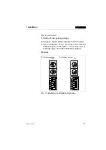
Страница 20: ...rewdriver to set the arrow of the relevant address switch or DIL switch 1 to the units tens or hundreds figure of the desired fieldbus address Examples Set fieldbus address Set fieldbus address 005 121 Fig 1 3 Example of set fieldbus addresses 6 5 2 7 8 9 0 1 3 4 6 5 2 7 8 9 0 1 3 4 1 Installation CP FB13 E 9904b 1 9 ...

Страница 21: ... baud rates below The maximum permitted fieldbus length depends on the baud rate used The baud rates which can be used are shown in the table below Baud rate in kBaud Fieldbus length max 9 6 1200 m 19 2 1200 m 93 75 1200 m 187 5 1000 m 500 400 m 1500 200 m 3000 12000 100 m 1 Installation 1 10 CP FB13 E 9904b ...

Страница 22: ...ount the sum of the branch lines The maximum permitted length of the branch line depends on the type of cable and baud rate used Recommendation Use a cable with a capacitance per unit length 30 nF km as specified below Otherwise the permitted cable length will be shorter Baud rate in kBaud Maximum permitted brauch line in m 9 6 500 19 2 500 93 75 100 187 5 33 3 500 20 1500 6 6 3000 12000 1 Install...

Страница 23: ...2 1 4 Connecting CP modules WARNING Use te CP cable KVI CP 1 to connect the input module to the node Please note that the maximum cable length on a string must not exceed 10 m You thereby avoid errors in data exchange between the node and the connected input modules Information on the procedure can be found in the ma nual CP system installation and commissioning 1 Installation 1 12 CP FB13 E 9904b...

Страница 24: ...805 Remark By using PELV power units protection against electric shock protection against direct and indirect contact in accordance with EN 60204 1 IEC 204 is guaranteed on Festo valve terminals Safety transformers with the adjacent designation must be used for supplying PELV networks The valve termi nals must be earthed in order to ensure their function e g EMC PLEASE NOTE Check your EMERGENCY ST...

Страница 25: ...e for Festo Sub D plug 6 9 mm Pin assignment view of socket Pin Signal Designation 1 2 3 4 5 6 7 8 9 Housing n c n c RxD TxD P CNTR P DGND VP n c RxD TxD N n c Shield Not connected Not connected Receive send data P Repeater control signal Data reference potential M5V Positive power supply P5V Not connected Receive send data N Not connected Direct connection to housing Repeater control signal CNTR ...

Страница 26: ...ip in the Festo plug is only capacitively connected internally with the metal housing of the Sub D plug This is to prevent equalizing currents from flowing via the screening of the fieldbus cable see diagram 1 2 Screening connection cable clip Only capacitively connected Fig 1 4 Connecting the screening 1 2 1 Installation CP FB13 E 9904b 1 15 ...

Страница 27: ...ommendation If the CP system is at the end of the fieldbus system a bus termination is required Use the Sub D plug from Festo part no 18529 for this purpose A suitable RC network has already been fitted into the housing of the Festo sub D plug The bus termination must be switched manually Bus termination switched on switched off Fig 1 5 Switch for bus termination in the Festo sub D plug 1 Installa...

Страница 28: ...Pin 6 Power supply Pin 3 RxD TxD P Pin 8 RxD TxD N Pin 5 DGND Fig 1 6 Bus termination for cable A 390 220 390 Pin 6 Pin 3 Pin 8 Pin 5 1 Installation CP FB13 E 9904b 1 17 ...

Страница 29: ...echnology offers the fol lowing advantages higher EMC ESD protection thanks to the optical transmission of signals protection against lightning potential isolation of the individual DP slaves equali zing currents cannot flow via the cable screening The PROFIBUS DP interface of the node has been de signed in accordance with specification EN 50170 vol ume 2 and thereby supports the control of networ...

Страница 30: ...Chapter 2 Commissioning 2 Commissioning CP FB13 E 9904b 2 1 ...

Страница 31: ... 2 19 PROFIBUS Configuration Help tool software 2 19 2 2 2 STEP 7 V4 x Hardware configurator 2 20 Prerequirements 2 20 Station selection and configuration 2 22 Addressing examples in standard mode 2 26 Addressing examples in compact mode 2 28 2 2 3 Commissioning the CP system on the PROFIBUS DP 2 30 2 3 Operation with general DP master 2 32 2 3 1 Starting the bus 2 32 2 3 2 Sending parametrizing d...

Страница 32: ...ASE NOTE The CP fieldbus node must be supplied with opera ting voltage by a suitable power unit 2 1 2 Saving the string assignment PLEASE NOTE Before commissioning the CP system you must first prepare the CP system for commissioning see CP system manual 2 Commissioning CP FB13 E 9904b 2 3 ...

Страница 33: ...voltage for the node see CP system manual 2 Connect the CP modules 3 Switch on the operating voltage 4 Save the string assignment by pressing the SAVE button 1 SAVE Button saves the configuration of the CP system as the ACTUAL configuration Fig 2 1 SAVE button 1 2 Commissioning 2 4 CP FB13 E 9904b ...

Страница 34: ...and the ACTUAL configuration saved in the CP fieldbus node in order to detect any connection errors Access these specifications during a syntax check of a program in order to avoid addressing errors Configuration of the CP system requires a very accur ate procedure as different configuration specifications may be rquired for each system due to the modular structure Please observe here also the spe...

Страница 35: ...ller Please refer here to the documentation for your field bus mo dule CAUTION In the following cases the FREEZE or SYNC mode is reset automatically when the CP system is switched on off when the field bus module is stopped The FREEZE is also reset automatically in the following case when the bus connection to the CP system is interrupted response monitoring active 2 Commissioning 2 6 CP FB13 E 99...

Страница 36: ...REEZE SYNC With this function all the outputs of the CP system can be frozen As a result the CP system no longer reacts to modifications to the output image in the master The following SYNC command causes the output image of the master to be updated and transferred You can return to normal mode with the command UNSYNC Module consistency The CP system supports the following variants in mo dule cons...

Страница 37: ...amples The configuration data must be known or determined for each bus slave There are two methods of configuring the CP system standard mode compact mode The CP system automatically recognizes the mode in which you wish to operate the CP system due to the DP identifier sent by the master WARNING Configure a CP system only in one of these two methods standard mode 4 x 049 compact mode sum identifi...

Страница 38: ...t 00 Spezific identifier formats 01 Input 10 Output 11 Input Output Lenght 0 byte 1 word Consistency 0 byte or word 1 total lenght Fig 2 2 Structure of identifier byte Example 00010000b 016d 010h 8DE 8 digital inputs 7 6 5 4 3 2 1 0 Bit Bit 2 Commissioning CP FB13 E 9904b 2 9 ...

Страница 39: ... 3 Standard mode possible configuration of the inputs and outputs The last used string is decisive for the number of I O addresses even if numerically lower strings are not oc cupied physically see manual CP system installation and commissioning Example CP system with 3 strings 3 input modules 3 output modules highest occupied string number 2 DP Identifier Comment 0 16DX I module und O module of s...

Страница 40: ...itted Assign the DP identifiers in ascending order without gaps No field may remain unused Enter inputs before outputs If there are only output modules or CP valve termi nals enter their DP identifiers in line 0 The highest string with the highest number of inputs or outputs defines the sum of input or output bytes Non existent CP valve terminals output modules or input modules occupy input or out...

Страница 41: ...tput Sum identifier decimal 0 2 033 16DO 1 4 035 32DO 2 6 037 3 8 039 Fig 2 5 Compact mode possible configurations of the inputs and outputs Example 1 CP system with 3 strings 3 input modules and 3 output modules highest occupied string number 2 DP identifier Comment 0 021 6 bytes per input 1 037 6 bytes per output Example 2 CP system with 3 strings only 3 output modules hig hest occupied string n...

Страница 42: ...tions 1 Copy the GSD of the valve terminals into the direc tory COMPB3x GSD of your PC programmer You will find the GSD on the accompanying CD ROM File VI10F13C GSE CD ROM Further information directories etc can be found in the file readme in the main directory of the CD ROM PLEASE NOTE Update the slave catalogue when you copy the GSD whilst working with COM PROFIBUS Menu File Load GSD file 2 Comm...

Страница 43: ...he CD ROM to simplify the configuration Copy the file PBFB13CN BMP into the directory COMPB3x BITMAPS on your PC programmer Symbols Further information directories etc can be found in the file readme in the main directory of the CD ROM Station selection Fig 2 6 Station selection with COM PROFIBUS 2 4 1 3 2 Commissioning 2 14 CP FB13 E 9904b ...

Страница 44: ...apter 1 2 1 in the slave and confirm this 4 The entry mask Slave parameters will appear Se lect the station type FESTO CP FB13 and confirm this 5 The mask Preset Configuration will now appear Select here the highest occupied string number and confirm this with OK Fig 2 8 Selecting the highest occupied string number The icon of the Festo valve terminal will now appear under the graphic of the maste...

Страница 45: ...S address has been assigned the station type FESTO CP FB13 has been se lected see above Access the mask Configure Configure 1 Double click with the left hand mouse key or single click with the right hand mouse key on the icon of the Festo valve terminal 2 Select Configure in the menu which appears The mask Configure will then appear Fig 2 8 2 Commissioning 2 16 CP FB13 E 9904b ...

Страница 46: ...he identifiers in standard mode in this mask Standard mode If you wish to use the compact mode proceed as fol lows Compact mode 1 Delete the identifiers for the standard mode 2 Enter the identifiers for the compact mode summary see Fig 2 5 2 Commissioning CP FB13 E 9904b 2 17 ...

Страница 47: ...2 bytes per input output 2 16DX String 2 2 bytes per output inputs not used Example 1 configuration Example 2 As example 1 but entry in compact mode DP identifier Comment 0 019 String 0 1 4 bytes per input 1 037 String 0 1 2 6 bytes per output Example 2 configuration Alternative entry via Identifier mask You can also enter the identifiers via a mask 1 Click the button Identifier in the mask Config...

Страница 48: ...ked I O address range the function Auto address carries out an automatic assignment of the free addresses in the system depending on the sys tem limits This completes the configuration address assignment with COM PROFIBUS PROFIBUS Configuration Help tool software In order to simplify configuration the CD ROM contains the PROFIBUS Configuration Help Tool software This software will enable you to as...

Страница 49: ...nu item Extras Install new GSD in the mask Hardware configuration Further information directories etc can be found in the file Readme in the main directory of the CD ROM PLEASE NOTE Update the hardware catalogue if you copy the GSD whilst working with STEP7 Menu in Hardware Configuration Extras Update catalogue PLEASE NOTE As from STEP7 V4 02 device master files GSD are stored in the STEP7 project...

Страница 50: ...ry STEP7 S7DATA NSBMP on your PC programmer Symbols The bit maps can be either copied manually into the above mentioned directory e g via Windows Explorer or loaded via menu item Extras Install new GSD file type Bit map in hardware configuration Further information directories etc can be found in the file readme in the main directory of the CD ROM 4 Activate the DP master in the rack 2 Commissioni...

Страница 51: ...ion selection and configuration Fig 2 9 Station selection with STEP7 V4 x hardware configuration the masks shown are not all visible at the same time see text 1 4 3 5 2 2 Commissioning 2 22 CP FB13 E 9904b ...

Страница 52: ...and mouse button pressed down and pull the cursor onto the graphic PROFIBUS line on the DP master drag and drop 4 The mask Selecting the Setpoint Configuration will appear Select here the highest occupied string number and confirm this with OK 5 The entry mask Properties PROFIBUS Node will appear Select the slave PROFIBUS address identical to the setting of the rotary switch DIL switch see Chapter...

Страница 53: ...erminal to be configured on the graphic surface of the hardware configuration 1 The configuration data appear with the columns Mo dule DPID Order Number I Address O Address and Comment in the table in the lower half of the screen 2 Addressing 1 2 2 Commissioning 2 24 CP FB13 E 9904b ...

Страница 54: ...double clicking the appropriate line in the configuration table 2 of the DP slave and modify the starting address of the inputs outputs 4 Select the identifiers as shown in the summary in Fig 2 5 The input and output addresses are assigned automat ically by STEP7 Proceed as follows if you wish to mod ify this address assignment Modify address Open the mask Properties DP slave by double click ing t...

Страница 55: ...ress IN OUT String 0 16 outputs and 16 electrical inputs 049 O 20 0 21 7 I 20 0 21 7 String 1 not assigned 049 O 22 0 23 7 I 22 0 23 7 String 2 16 outputs and 16 electrical inputs 049 O 24 0 25 7 I 24 0 25 7 String 3 not assigned Address range for other bus slaves See also Fig 2 11 2 Commissioning 2 26 CP FB13 E 9904b ...

Страница 56: ... 3 2 SAVE POWER 24 VDC POWER V ERROR PROFIBUS DP BUS ERROR Octet 1 Bits 0 7 A20 0 A20 7 Octet 2 Bits 0 7 Octet 1 Bits 0 7 E20 0 E20 7 Octet 2 Bits 0 7 E21 0 E21 7 Octet 3 Bits 0 7 Octet 4 Bits 0 7 Octet 3 Bits 0 7 Octet 4 Bits 0 7 Octet 5 Bits 0 7 A24 0 A24 7 Octet 6 Bits 0 7 Octet 5 Bits 0 7 E24 0 E24 7 Octet 6 Bits 0 7 E25 0 E25 7 2 Commissioning CP FB13 E 9904b 2 27 ...

Страница 57: ...ystem DP identifier I O address IN OUT String 0 8 outputs 017 037 O 20 0 20 7 I 20 0 21 7 unused String 1 16 inputs O 22 0 23 7 unused I 22 0 23 7 String 2 16 outputs O 24 0 25 7 String 3 not assigned Address range for other bus slaves See also Fig 2 12 2 Commissioning 2 28 CP FB13 E 9904b ...

Страница 58: ...puts and inputs of a CP system on the PROFIBUS DP in compact mode Octet 1 Bits 0 7 Octet 2 Bits 0 7 Octet 5 Bits 0 7 A24 0 A24 7 Octet 6 Bits 0 7 A25 0 A25 7 Octet 3 Octet 4 Octet 5 Bits 0 7 A24 0 A24 7 Octet 6 Bits 0 7 A25 0 A25 7 Octet 3 Bits 0 7 E22 0 E22 7 Octet 4 Bits 0 7 E23 0 E23 7 No more input bytes occupied 2 Commissioning CP FB13 E 9904b 2 29 ...

Страница 59: ...ch on the operating voltage for the master module When switched on some master systems will automat ically carry out a comparison between the NOMINAL and ACTUAL configurations For this configuration run it is important that Configura tion run the specifications on the NOMINAL configuration are complete and correct see also section 2 1 2 the power supplies to the PLC and to the fieldbus slaves are ...

Страница 60: ... voltages pins 1 and 2 but without com pressed air In this way you have the possibility of testing without the risk of unintentional reactions PLEASE NOTE A CP valve location occupies two addresses The following applies lower value address pilot solenoid 14 higher value address pilot solenoid 12 2 Commissioning CP FB13 E 9904b 2 31 ...

Страница 61: ... mode can be found in section 2 1 4 2 3 1 Starting the bus In order to operate the CP system correctly the DP master must perform the following functions in the se quence specified 1 Send a parametrizing telegram 2 Send a configuration telegram 3 Request diagnostic information 4 Start useful cyclic data transmission The structure and content of the individual telegrams are described in subsequent ...

Страница 62: ... Freeze_Req logic 0 Freeze mode not requested by the master logic 1 Freeze mode not activated by the master 5 Sync_Req logic 0 Sync mode not requested by the master logic 1 Sync mode not activated by the master 6 Unlock_Req Bit 7 Bit 6 Explanation 7 Lock_Req 0 0 min TSDR CP system parameters may be overwritten 0 1 CP system released for other masters 1 0 CP system blocked for other masters 1 1 CP ...

Страница 63: ...hich the CP system must wait before the reply telegram may be sent to the DP master Octets 5 and 6 Ident_Number Explanation Transfer the Ident number FB9C of the CP system Parametrizing telegrams to the CP system are only accepted when the transferred and the programmed Ident numbers are identical Octet 7 Group_Ident Explanation Not supported by the CP system Octet 8 32 User_Prm_Data Explanation N...

Страница 64: ...ifier for inputs and outputs via sum identifier sum of the input bytes and sum of the output bytes The structure of the identifier byte can be found in sec tion 2 1 4 Parameter summary Chk_Cfg Octet 1 n DP Identifier Permitted identifiers for Festo CP systems in compact mode see also Fig 2 5 No of I Os Inputs decimal Outputs decimal up to 16 017 033 up to 32 019 035 up to 48 021 037 up to 64 023 0...

Страница 65: ...hapter 3 Diagnosis via PROFIBUS DP 2 3 5 Cyclic exchange of data The cyclic exchange of data is carried out with the func tion Data_Exchange With this function the output data for CP systems are transferred as an octet string of length x The octet string length is determined by the number of identifier bytes PLEASE NOTE With the function Data_Exchange the CP system expects the output information f...

Страница 66: ...tput x 6 Bit 7 input output x 7 Octet 2 I O data byte_2 Bit 0 input output x 8 Bit 1 input output x 9 Bit 7 input output x 15 Octet 8 I O data byte_8 Bit 0 input output x s Bit 1 input output x t Bit 2 input output x u Bit 3 input output x v Bit 4 input output x w Bit 5 input output x x Bit 6 input output x y Bit 7 input output x z x Address offset of the master module 2 Commissioning CP FB13 E 99...

Страница 67: ... access points SAP Function Available Destination SAP DSAP Data_Exchange Yes NIL RD_Inp Yes 56 RD_Outp Yes 57 Slave_Diag Yes 60 Set_Prm Yes 61 Chk_Cfg Yes 62 Get_Cfg Yes 59 Global_Control Yes 58 Set_Slave_Add No 55 2 Commissioning 2 38 CP FB13 E 9904b ...

Страница 68: ...ion times on the PROFIBUS DP PLEASE NOTE Observe also the cycle time of your PLC and the update time of the PROFIBUS DP The delay time within the CP system depends on the amount of data and therefore on the string assignment 5 ms The calculation of the complete transmission time can be found in the controller manual 2 Commissioning CP FB13 E 9904b 2 39 ...

Страница 69: ...file Readme on the diskette The device master file contains a selection of identifiers in addition to the slave typical entries ident number re vision etc Enter the identifiers for the CP system in the following sequence 1 Digital inputs 2 Digital outputs Example CP system with 2 valve terminals and 2 input modules CP system last used string Identifier Assigned address range 0 1 049 049 16 inputs ...

Страница 70: ...Chapter 3 Diagnosis 3 Diagnosis CP FB13 E 9904b 3 1 ...

Страница 71: ...1 3 12 Structure of station status 2 3 13 Structure of station status 3 3 13 Master address 3 14 Manufacturer identifier 3 14 Header device related diagnosis 3 14 Structure of device related diagnosis 1 3 15 Structure of device related diagnosis 2 5 3 16 3 4 Error treatment 3 17 3 4 1 General DP master 3 18 3 4 2 Siemens SIMATIC S5 S7 3 18 Possibilities of reading the diagnosis for S5 S7 3 20 3 5 ...

Страница 72: ...ermit fast on the spot diag nosis of the operating status of the CP system 1 2 3 BUS LED Operating voltage LEDs String LEDs Fig 3 1 LEDs on the CP node FB13 0 1 3 2 SAVE POWER 24 VDC POWER V ERROR PROFIBUS DP BUS ERROR 3 2 1 3 Diagnosis CP FB13 E 9904b 3 3 ...

Страница 73: ... of valves Lights up if operating voltage of valves is ok pin 2 blinks if operating voltage is 20 4 V 0 3 CP string LED During start up phase blinks if the string assignment has been changed since the last operation during operation lights up if a CP connection has been interrupted 3 1 1 Normal operating status In normal operating status the following LEDs light up on CP node 13 lights up LED flas...

Страница 74: ...f LED BUS ERROR None Check the compressed air supply pilot exhaust channels See error message of LED BUS ERROR POWER POWER V Operating voltage of outputs pin 2 not applied CP valve terminal or output module defective Replace CP module POWER POWER V Operating voltage of outputs pin 2 not in tolerance range Check operating voltage of outputs pin 2 POWER Operating voltage of electronic components pin...

Страница 75: ...ct station number BUS at 1 s intervals Fieldbus connection not correct Possible causes Station number not correct e g address assigned twice fieldbus module switched off or defective interrupted short circuited or faulty fieldbus connection Configuration not correct Check nominal actual status Check the setting of the address selector switch fieldbus module fieldbus connection configuration BUS Va...

Страница 76: ...ents of the actua tors the need to press the SAVE button again CAUTION This test function runs automatically within the CP valve terminals All the valves are switched on off cyclically None of the programmed locking or switching conditions will be taken into account During the test routine of the CP valve terminal all the valves will be switched on and off at 1 s intervals Test routine 3 Diagnosis...

Страница 77: ...ge supplies pins 1 and 2 7 Start the test routine by setting DIL switch element 1 to OFF If errors occur when the test routine is started the red LED on the node will flash fast The process must then be repeated Stopping the test routine 1 Switch off the operating voltage supplies pins 1 and 2 at the node 2 Reset the address selector switch and the DIL switch elements to their original positions S...

Страница 78: ...oad voltage drop on the output modules short circuit overload at the output modules interruption of the CP connection at various CP modules Additional error messages DIL switch 2 ON load voltage drop at the CP connection voltage for CP valves below tolerance level 20 4 V Busy bit With device related diagnosis 1 the CP system sup plies status information as bit 1 Busy bit CP system in start up phas...

Страница 79: ...teps necessary for diagnosing the CP system Only those diagnostic bits are shown which require a further diagnostic step Read device related diagnosis 1 Read device related diagnoses 2 5 Bit Station status 1 Bit Device related diagnosis 1 Fig 3 2 Diagnostic steps 7 6 5 4 3 2 1 0 1 7 6 5 4 3 2 1 0 1 3 Diagnosis 3 10 CP FB13 E 9904b ...

Страница 80: ...master_Add 4 3 4 5 Manufacturer identifier Ident_number High byte F1H Manufacturer identifier Ident_number Low byte 3CH 6 5 6 7 Header Device related diagnosis 1 Error summary 8 7 8 9 Device related diagnosis 2 error byte CP string 0 Device related diagnosis 3 error byte CP string 1 10 9 10 11 Device related diagnosis 4 error byte CP string 2 Device related diagnosis 5 error byte CP string 3 12 11...

Страница 81: ...ted interference in data cable 1 Diag Station_Not_Ready CP system not yet ready for exchange of data 2 Diag Cfg_Fault The configuration data received from the master do not correspond to those ascertained by the CP system 3 Diag Ext_Diag There is a device related diagnosis Possible causes cable interrupted at I O module short circuit overload at electrical outputs Vvalves 20 4 V Voutputs 10 V Vsen...

Страница 82: ...tem 3 Diag WD_On Logic 1 watchdog activated 4 Diag Freeze_Mode logic 0 Freeze activated 5 Diag Sync_Mode logic 0 Sync activated 6 Reserved 7 Diag Deactivated Always logic 0 set by CP system Fig 3 5 Diagnostic bits of station status_2 Structure of station status 3 Octet 3 Station status_3 Bit Meaning Explanation 0 Reserved 1 2 3 4 5 6 7 Diag Ext_ Diag_Overflow Always logic 0 set by CP system Fig 3 ...

Страница 83: ...he Festo CP system Fig 3 8 Diagnosis Ident_Number Header device related diagnosis Octet 7 Ext_Diag_Data device related diagnosis Explanation This octet represents the header for the device diagnosis The CP system enters the fixed value 8 in this octet i e 8 octets device related diagnosis are made available transferred incl header octet This value is independent of the equipment fitted onto the CP...

Страница 84: ... Busy Bit Logic 1 during the start up phase CP system not yet ready for exchange of data 2 Not assigned 3 Not assigned 4 Common error 0 Logic 1 error in string 0 5 Common error 1 Logic 1 error in string 1 6 Common error 2 Logic 1 error in string 2 7 Common error 3 Logic 1 error in string 3 Fig 3 10 Diagnostic bits of device related diagnosis 1 3 Diagnosis CP FB13 E 9904b 3 15 ...

Страница 85: ...osis 2 5 Bit Meaning Explanation 0 Iout Logic 1 CP connection interrupted at output module 1 Iinp Logic 1 CP connection interrupted at input module 2 Short circuit overload Logic 1 short circuit overload at output module 3 Vout Logic 1 load voltage drop at output module 4 Vsen Logic 1 voltage supply to sensors 10 V 5 Vval Logic 1 voltage supply to valve coils 20 4 V 6 Vload Logic 1 voltage supply ...

Страница 86: ...ed off or maintain their status WARNING Make sure that the valves and outputs are reset after rectifying the above mentioned faults Dangerous situations can arise if the valves and out puts are not reset after one of the above faults PLEASE NOTE Single solenoid valves move to the basic position double solenoid valves remain in the current position If mid position functions are implemented by CP va...

Страница 87: ...me 3 4 2 Siemens SIMATIC S5 S7 With these controllers you can determine the reaction of the CP system to the faults named details see con troller manual Almost all configuration programs contain the function Response monitoring For the operating modes named the specified time corresponds to the drop off time of the valves and the electrical outputs Further details on response monitoring can be fou...

Страница 88: ...ith IM 308C OB23 Reaction to QVZ with direct periphery access default OB is programmed OB24 Reaction to QVZ with periphery access via process image default OB is programmed OB35 Reaction to PEU periphery unclear default OB is programmed SIMATIC S7 M7 OB82 Reaction to device specific diagnosis default OB is programmed OB86 Reaction to failure of a DP slave default OB is programmed Further details c...

Страница 89: ...tral periphery system ET 200 Siemens SIMATIC S5 with SF 50 DP master FB 230 S_DIAG Manual Programmable valve terminal with SB SF 50 Festo SIMATIC S7 M7 SFC 13 DP NRM_DG Reference manual System and standard functions Siemens Example of a STEP 7 user program STL Explanation CALL SFC 13 REQ TRUE Request to read LADDR W 16 03FE Pointer to diagnostic address e g 1022d 03FEh see mask Features DP slave i...

Страница 90: ...stic buffer The diagnostic buffer of STEP7 offers the possibility of displaying diagnostic events of the S7 system in the sequence in which they occur Fig 3 13 Online diagnosis via diagnostic buffer 1 2 3 4 5 6 5 3 Diagnosis CP FB13 E 9904b 3 21 ...

Страница 91: ... with the periphery valve terminal has incorrect DIL rotary switch setting Prerequirements the hardware configuration must be accessed Proceed as follows Fig 3 13 1 Switch from offline to online 2 Use the right hand mouse key to mark the CPU in the rack Click Module Information in the menu which now appears 3 The window Module Information now appears 4 Select the rider Diagnostic buffer 5 Mark the...

Страница 92: ...he Festo valve terminal 6 Mark the Festo valve terminal instead of the CPU By means of the window Module Information you can read out more information on the status of the valve terminal 3 Diagnosis CP FB13 E 9904b 3 23 ...

Страница 93: ...eset error In order to reset the error the 8 outputs must be reset The following possibilities are available Possibilities Explanation Set all outputs of the output module to logic 0 RESET or Briefly interrupt CP connection on the CP output module or Briefly interrupt operating voltage of the CP system on the fieldbus node manually or automatically in the program Outputs of the output module are r...

Страница 94: ...ogic 1 PLEASE NOTE The inputs cannot be used until the short circuit or overload is eliminated and the error reset Reset error In order to reset the error the following possibilities are available Briefly interrupt the CP connection on the CP input module or Briefly interrupt the operating voltage of the CP system on the fieldbus node The inputs can then be interrogated again If the short circuit ...

Страница 95: ...3 Diagnosis 3 26 CP FB13 E 9904b ...

Страница 96: ...Appendix A Technical specifications A Technical specifications and index CP FB13 E 9904b A 1 ...

Страница 97: ...Contents A Technical specifications A 1 Technical specifications of fieldbus node CP FB13 E A 3 A 2 Index A 5 A Technical specifications and index A 2 CP FB13 E 9904b ...

Страница 98: ...irect and indirect contact as per EN 60204 1 IEC 204 By means of PELV power units protected extra low voltage Operating voltage of electronic components and input modules Pin 1 Operating voltage connection rated value tolerance 24 V DC 20 4 26 4 V Current consumption pin 1 node FB13 E all electronic components in CP system 250 mA see manual CP system chapter 3 1 2 Table of current consumption Resi...

Страница 99: ...ansmission type serial asynchronous half duplex Protocols PROFIBUS DP Baud rate 9 6 12000 kBaud Automatic baud rate recognition Cable length dependent on baud rate and cable type up to 23 8 km Cable type dependent on cable length and field bus baud rate set See controller manual Maximum loading Positive power supply P5V pin 6 max 40 mA Electromagnetic compatibility Interference emission tested as ...

Страница 100: ...onfiguration list 2 5 compiling 2 5 Configuration run 2 30 Connecting CP modules 1 12 operating voltage 1 13 PROFIBUS DP interface 1 14 screening 1 15 CP system operating voltage 2 3 preparing for operation on the PROFIBUS DP 2 3 A Technical specifications and index CP FB13 E 9904b A 5 ...

Страница 101: ...nostic information 2 36 general 2 32 implemented functions 2 38 send parametrizing data 2 33 service access points SAP 2 38 E Error treatment 3 17 short circuit overload at output 3 24 short circuit at input 3 25 F FREEZE 2 6 2 7 G General DP master send parametrizing data 2 33 GSD device master file 2 40 A Technical specifications and index A 6 CP FB13 E 9904b ...

Страница 102: ...le consistency 2 7 N Nominal actual configurations 2 5 O Operating status 3 4 Operating voltage CP system 2 3 P Pictograms VIII POWER LEDs diagnosis 3 5 PROFIBUS DP diagnostic information 3 12 PROFIBUS DP interface cable termination 1 16 connecting 1 14 A Technical specifications and index CP FB13 E 9904b A 7 ...

Страница 103: ...Siemens master configuration 2 13 diagnosis 3 9 String assignment saving 2 3 Switching status valves 3 7 SYNC 2 6 2 7 T Target group V Technical specifications A 3 Test routine for valves 3 7 finishing 3 8 starting 3 8 Type file 2 40 U User instructions VII A Technical specifications and index A 8 CP FB13 E 9904b ...

Отзывы: