Contents
Designated use. . . . . . . . . . . . . . . . . . . . . . . . . . . . . . . . . . . . . . . . . . . . . . V
Target group . . . . . . . . . . . . . . . . . . . . . . . . . . . . . . . . . . . . . . . . . . . . . . . . V
Information on this manual . . . . . . . . . . . . . . . . . . . . . . . . . . . . . . . . . . . VI
Important user instructions . . . . . . . . . . . . . . . . . . . . . . . . . . . . . . . . . . . VII
1. Installation
1.1
General instructions . . . . . . . . . . . . . . . . . . . . . . . . . . . . . . . . . . . 1-3
1.2
Setting the DIL switches . . . . . . . . . . . . . . . . . . . . . . . . . . . . . . . 1-4
1.2.2
Setting the fieldbus address. . . . . . . . . . . . . . . . . . . . . . . . . . . . 1-7
1.3
Fieldbus baud rate and fieldbus length . . . . . . . . . . . . . . . . . . . 1-10
1.3.1
Branch line length. . . . . . . . . . . . . . . . . . . . . . . . . . . . . . . . . . . . 1-11
1.4
Connecting CP modules . . . . . . . . . . . . . . . . . . . . . . . . . . . . . . 1-12
1.5
Connecting the operating voltage . . . . . . . . . . . . . . . . . . . . . . . 1-13
1.6
Connecting the PROFIBUS DP interface . . . . . . . . . . . . . . . . . 1-14
1.6.1
Connecting the screening. . . . . . . . . . . . . . . . . . . . . . . . . . . . . 1-15
1.6.2
Bus termination with terminating resistors . . . . . . . . . . . . . . . 1-16
1.6.3
Optical fibre waveguide connection . . . . . . . . . . . . . . . . . . . . . 1-18
2. Commissioning
2.1
Preparing the CP system for operation
on the PROFIBUS-DP . . . . . . . . . . . . . . . . . . . . . . . . . . . . . . . . 2-3
2.1.1
Operating voltage . . . . . . . . . . . . . . . . . . . . . . . . . . . . . . . . . . . 2-3
2.1.2
Saving the string assignment . . . . . . . . . . . . . . . . . . . . . . . . . . . 2-3
2.1.3
Compiling the configuration list . . . . . . . . . . . . . . . . . . . . . . . . . 2-5
2.1.4
General . . . . . . . . . . . . . . . . . . . . . . . . . . . . . . . . . . . . . . . . . . . . 2-6
2.2
Configuration with a Siemens master . . . . . . . . . . . . . . . . . . . . 2-13
2.2.1
COM PROFIBUS . . . . . . . . . . . . . . . . . . . . . . . . . . . . . . . . . . . 2-13
2.2.2
STEP 7 V4.x - Hardware configurator . . . . . . . . . . . . . . . . . . . 2-20
2.2.3
Commissioning the CP system on the PROFIBUS-DP . . . . . . 2-30
Contents and general safety instructions
CP FB13-E 9904b
III
Содержание Compact Performance CP-FB9-E
Страница 12: ...Chapter 1 Installation 1 Installation CP FB13 E 9904b 1 1 ...
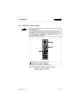
Страница 16: ...1 2 DIL switch Cover screws Fig 1 1 Position of the DIL switch 2 1 1 Installation CP FB13 E 9904b 1 5 ...
Страница 30: ...Chapter 2 Commissioning 2 Commissioning CP FB13 E 9904b 2 1 ...
Страница 70: ...Chapter 3 Diagnosis 3 Diagnosis CP FB13 E 9904b 3 1 ...
Страница 95: ...3 Diagnosis 3 26 CP FB13 E 9904b ...
Страница 96: ...Appendix A Technical specifications A Technical specifications and index CP FB13 E 9904b A 1 ...


