


30
Festo — CMMT-ST-C8-1C-...-S0 — 2021-04b
Technical data
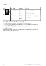
Control inputs #STO-A and #STO-B at [X1A]
Min. input voltage, low
level (U
L min
)
[V]
–3
Max. input current with
high level (I
H max
)
[mA]
15
Min. input current with
high level (I
H min
)
[mA]
8
Max. input current with
low level (I
L max
)
[mA]
0.5
Tolerance for low test pulses
Tolerated low test
pulses (t
STO,TP
) up to
max.
[ms]
1
Min. time between low
test pulses
[ms]
50
Tolerance for high test pulses
2)
Tolerated high test
pulses (t
STO,TP
) up to
max.
[ms]
1
Min. time between
high test pulses at
U
STO-A/B
<
U
L max
[ms]
50
1) Each channel has a separate overvoltage monitor for the power supply at the input. If the voltage at the input exceeds the permissible
maximum value, the channel is shut down.
2) High test pulses must never occur simultaneously at inputs #STO-A and #STO-B, but only with a time offset.
Tab. 19: Control inputs #STO-A and #STO-B at [X1A]
Diagnostic contact STA at [X1A]
Design
Potential-free contact
Voltage range
[V DC]
18 … 30
Max. current
[mA]
100 (not short-circuit proof)
Max. internal resist-
ance
[Ω]
< 6
Off-state current (con-
tact open)
[µA]
< 2
Closing reaction time
t
STA,Rise
[ms]
.
80 (typ. 20)
Opening reaction time
t
STA,Fall
[ms]
≤ 50 (typ. 30)


