Festo CMMT-ST-C8-1C-...-S0 Series Скачать руководство пользователя страница 13

Festo — CMMT-ST-C8-1C-...-S0 — 2021-04b

Product overview

13

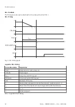
• If there are suspended loads and a motor with holding brake is used, they usually drop if STO is

requested immediately before the braking ramp has elapsed, because the engagement time of
the holding brake plays a significant role.

• The time t

3

 must always be set to a value longer than the total of the braking ramp time t

1

 and the

brake engagement time (t

2

 – t

1

). This prevents the following:

• Suspended loads potentially dropping
• Increased wear on the holding brake

When selecting the delay time t

Delay

, make sure it is long enough to take account of the maximum

braking ramp time and brake engagement time.
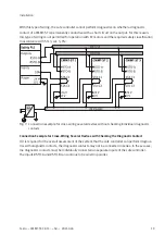
4.1.4

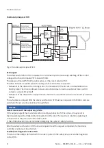
Cross-wiring of several servo drives

Whether cross-wiring of the diagnostic contact is permissible depends on the safety classification
required.
The diagnostic contact must be evaluated separately for EC motors with the classification SIL 3, cat. 3,
PL e. It is not permissible to cross-wire the diagnostic contact. In all other cases, the following rules
apply when cross-wiring several servo drives:

Wire inputs #STO-A and #STO-B in parallel in each case.

Wire diagnostic contacts STA-C1/C2 in series in each case.

Wire the diagnostic contacts of a maximum of 10 servo drives in series. The maximum cable length
applies to the entire line, from the safety relay unit to the final device.

Example of cross-wiring 

è

 5.5 Connection Examples, Cross-wiring.

4.1.5

Fault exclusion

Put suitable measures in place to prevent faulty wiring:

Exclude wiring faults in accordance with EN 61800-5-2

Configure the safety relay unit to monitor the outputs of the safety relay unit and wiring up to the
servo drive

4.1.6

Safety relay unit

Use suitable safety relay units with the following characteristics:

2-channel outputs with

Detection of shorts across contacts

Required output current (also for STO)

Evaluation of the diagnostic contact of the servo drive

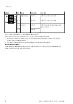
Safety relay units with test pulses can be used with the following restrictions:

High test pulses up to a maximum length of 1 ms

Low test pulses up to a maximum length of 1 ms

Test pulses are not simultaneous/overlapping on #STO-A/B

The safety relay units Pilz PNOZmulti, Pilz PNOZmulti Mini or SIEMENS SIMATIC ET 200SP with
PP-switching output modules, SIEMENS ET 200S, for example, would be suitable.
The input module CPX-F8DE and output module CPX-FVDA-P2 from Festo would be suitable too.
Comment: The safe output module CPX-FVDA-P2 can only switch potential-free loads. It can only be
used, therefore, in combination with an interposed relay, since #STO-A and #STO-B are referred to

Содержание CMMT-ST-C8-1C-...-S0 Series

Страница 1: ...CMMT ST C8 1C S0 Servo drive Manual Safety sub function STO SS1 t 8154451 2021 04b 8154453...

Страница 2: ...Translation of the original instructions ET 200 PNOZ Pilz SIEMENS ET 200SP are registered trademarks of the respective trademark owners in certain countries...

Страница 3: ...4 1 1 Function and application 7 4 1 2 Safety sub function STO 7 4 1 3 Safety sub function SS1 t 11 4 1 4 Cross wiring of several servo drives 13 4 1 5 Fault exclusion 13 4 1 6 Safety relay unit 13 4...

Страница 4: ...documents for the product www festo com sp 1 3 Product version This documentation refers to the following version Servo drive CMMT ST S0 revision 1 and higher see product labelling 1 4 Product labell...

Страница 5: ...nexpected restart of the motor The safety sub function SS1 t is intended to perform a fast stop with subsequent torque switch off Ensure that wiring is cross circuit proof in accordance with EN ISO 13...

Страница 6: ...ion of SIL 3 cat 3 Pl e without evaluation of the diagnostic contact STA Operation of the connected motor without the danger zone being restricted or enclosed by suitable means The user must not be ab...

Страница 7: ...when the power supply to the motor needs to be switched off safely in the application but there are no further requirements for a targeted standstill of the drive such as stop category 1 from EN 6020...

Страница 8: ...pped motor the drive is uncontrolled and can be moved by external forces The safe state is achieved after the safety sub function STO has been requested if all motor coils are switched off and current...

Страница 9: ...vel High level High level Tab 2 State of the diagnostic contact STA If the safety sub function STO is not requested but protective functions are triggered simultaneously on both channels STO A and STO...

Страница 10: ...A STO B 2 channel input for STO request STO PWM1 STO PWM2 Internal control PWM driver 1 and 2 tSTO TP Length low test pulses1 at STO A B tSTO In Max delay until STO switches off permissible reaction...

Страница 11: ...ime delay triggering of the safety subfunction STO Requirements of SS1 t Wire the safety sub function STO Execute emergency stop command by means of the safety relay unit either directly by wiring CTR...

Страница 12: ...iming Term abbreviation Explanation Timer Delay element in safety relay unit CTRL EN Enable signal tDelay Delay time until STO request STO A B 2 channel input for STO request STA Feedback STO active t...

Страница 13: ...stic contacts of a maximum of 10 servo drives in series The maximum cable length applies to the entire line from the safety relay unit to the final device Example of cross wiring 5 5 Connection Exampl...

Страница 14: ...N 60204 1 Comprehensive information concerning the electrical installation of the device Manual Assembly Installation Information for operation with safety functions NOTICE Check the safety functions...

Страница 15: ...tallation The safety relay unit and its inputs and outputs must meet the necessary safety classification of the safety function required for the specific case Connect each of the control inputs to the...

Страница 16: ...the safety sub function STO The motor controller cannot detect a cross circuit in the input circuit by itself 1 Find out if detection of shorts across contacts is needed for the input circuit and diag...

Страница 17: ...t is passed on to the servo drive on 2 channels via the inputs STO A and STO B at the connection X1A This safety request results in the 2 channel switch off of the driver supply to the servo drive s p...

Страница 18: ...n STO but is supplemented by an emergency stop request either directly by wiring CTRL EN or indirectly via another functional controller so that the braking ramp can be activated by the safety relay u...

Страница 19: ...cat 3 Ple Fig 7 Connection example for cross wiring several devices without checking individual diagnostic contacts Connection Example for Cross Wiring Several Devices with Checking the Diagnostic Co...

Страница 20: ...s described below Devices with diagnostic output must always be wired in parallel e g all CMMT AS The signal must then be connected to the diagnostic contact of the first CMMT ST The diagnostic contac...

Страница 21: ...ic contact CMMT ST and diagnostic output e g CMMT AS 6 Commissioning 6 1 Safety Use of safety functions NOTICE The safety sub function STO is already available on the servo drive on delivery without t...

Страница 22: ...e overall system to calculate the required safety classification for the CMMT ST and to assess whether the CMMT ST is suitable for their application The following check lists are no substitute for saf...

Страница 23: ...be inspected as a minimum as part of the validation Yes o No o o 3a Inspection of components is the servo drive described here being used check using the rating plate Yes o No o o 3b Is the wiring cor...

Страница 24: ...ation The system manufacturer must guarantee the following steps are taken in order to integrate the safety sub function of the CMMT ST into their overall system Provide evidence of a system of projec...

Страница 25: ...additional communica tion interfaces bus commissioning software LED Meaning Flashe s red Error in the safety part or a safety condition has been violated Illumi nated yellow The safety sub function h...

Страница 26: ...cifications Safety reference data for the safety sub function STO Circuitry Stepper motor EC motor without evaluation of STA EC motor with eval uation of STA Safety sub function in accordance with EN...

Страница 27: ...y unit is required or optional 2 To achieve the safety classification SIL 3 cat 3 PL e with stepper motor the evaluation of the diagnostic contact STA is optional An annual test interval is recommende...

Страница 28: ...eight kg Approx 0 35 Tab 14 General technical data Ambient conditions transport in original packaging or in control cabinet Transport temperature C 25 70 Relative humidity 5 95 non condensing Max tran...

Страница 29: ...resistance in accordance with EN 61800 2 EMC in accordance with EN 61800 5 2 Tab 17 Ambient conditions operation Service life Service life of the device at rated load h 25000 Dependent on the required...

Страница 30: ...Min time between high test pulses at USTO A B UL max ms 50 1 Each channel has a separate overvoltage monitor for the power supply at the input If the voltage at the input exceeds the permissible maxi...

Страница 31: ...MMT ST C8 1C S0 2021 04b Technical data 31 Diagnostic contact STA at X1A Galvanic isolation Via optocoupler Protective functions Overvoltage resistant up to 60 V DC Tab 20 Diagnostic contact STA C1 C2...

Страница 32: ...2021 all rights reserved to Festo SE Co KG Copyright Festo SE Co KG 73734 Esslingen Ruiter Stra e 82 Deutschland Phone 49 711 347 0 Internet www festo com...

Отзывы: