


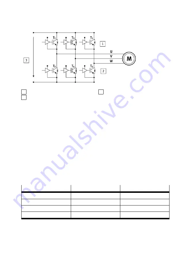
1 High-side output stage
2 Low-side output stage
3 Intermediate circuit voltage
Fig. 3 Output stage with power transistors
STO request
The STO safety function is requested over 2 channels by switching off the control voltage at both con-
trol ports #STO-A and #STO-B.
The drive behaves as follows when the STO safety function is requested:
–
Behaviour of the drive with a running motor: The movement of the drive is not decelerated via a
braking ramp. The drive continues to move uncontrolled due to inertia or external forces until it
comes to a standstill by itself.
–
Behaviour of the drive with a stopped motor: The drive is uncontrolled and can be moved through
external forces.
STO feedback through STA diagnostic contact
The status of the STO safety function can be reported to the safety relay unit through the STA dia-
gnostic output.
The STA diagnostic output displays whether the safe status has been reached for the STO safety func-
tions. The STA diagnostic output switches to high level only when STO is active in 2 channels through
the control inputs #STO-A and #STO-B.
#STO-A
#STO-B
STA
Low level
Low level
High level
Low level
High level
Low level
High level
Low level
Low level
High level
High level
Low level
Tab. 2 Level STA
If protective functions are triggered in both channels (STO-A and STO-B), e.g. with excessive voltage
at STO-A and STO-B, the internal protective functions switch off and STA likewise delivers high level.
Product overview
9
Festo — CMMT-AS-...-S1 — 2018-02