


If there are suspended loads, they usually drop if STO and SBC are requested immediately after the
braking ramp has elapsed since the engagement time of the holding brakes is not insignificant. This
can be avoided if the safety relay unit initially triggers only SBC on expiry of the braking ramp, so that
one holding brake or clamping unit that is present is engaged while the closed-loop controller is still
active. After elapse of the time until the brakes are closed, the safety relay unit can then trigger STO
(time-delayed linkage of the safety functions SS1
è
SBC
è
STO).
Wiring of the safety function STO to SBC
è
4.1.5
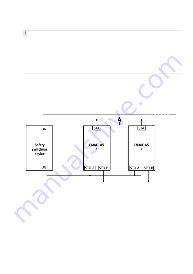
Cross wiring of several servo drives
For cross wiring, wire the diagnostic outputs as a ring. Route both ends of the ring to a 2-channel input
of the safety relay unit. The safety relay unit monitors for discrepancies. A maximum of 10 servo drives
can be wired in parallel.
Cross-wiring, example STA
Fig. 11 Cross-wiring, example STA
For cross-wired diagnostic outputs, the condensed state results from a logical AND link. An output of a
CMMT-AS is capable of pulling all other outputs to low signal. A high signal is present at the two
inputs of the safety relay unit only if all diagnostic outputs deliver high signals. The ring-shaped cross
wiring of the diagnostic outputs with sensing at the beginning and end of the signal chain makes it
possible to detect cable breaks in the cross wiring.
At this point, the diagnostic outputs deviate from the closed current principle. Cyclical automatic test-
ing of the diagnostic output by the safety relay unit is therefore highly recommended
è
STO feedback through STA diagnostic contact and
è
SBC feedback through SBA diagnostic contact.
Product overview
19
Festo — CMMT-AS-...-S1 — 2018-02