


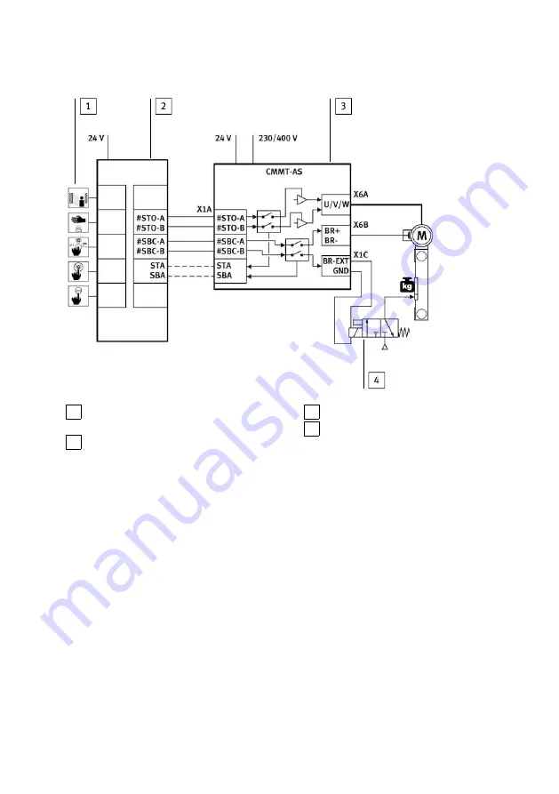
1 Input device for safety request (e.g. light cur-
tain)
2 Safety relay unit
3 Servo drive CMMT-AS
4 Control (here solenoid valve example) of the
clamping unit
Fig. 14 SBC sample circuit
Information on the sample circuit
The safety request is passed on through 2 channels over the inputs #SBC-A and #SBC-B at the connec-
tion [X1A] to the servo drive.
–
The request over the input #SBC-A switches off power to the signals BR+ and BR- at the connec-
tion [X6B]. Through this, the holding brake is de-energised and closes.
–
The request over the input #SBC-B switches off power to the signal BR-EXT at the connection
[X1C]. This shuts off power to the control of the external clamping unit. The clamping unit closes.
–
The safety relay unit monitors the SBA diagnostic output and checks whether the safe status has
been reached for the SBC safety functions.
5.4
SS1 installation
Inputs and outputs for the SS1 safety functions
The SS1 safety function is wired like the STO safety function, supplemented by the functional input
CTRL-EN for activation of the braking ramp through the safety relay unit.
SS1 connection example
Installation
25
Festo — CMMT-AS-...-S1 — 2018-02