EN
5
Ferm
Warning: This tool must be placed on its
stand when not in use.
Below, we give you some examples of poorly
soldered joints:
• If the soldering tin is tear-shaped, the
soldering coagulate was too cold.
• If the soldering tin is dull and slightly porous or
crystalline, the parts were probably moved
during the cooling process.
• If too little soldering tin has been left in the
joint, the soldering was too warm or the
soldering tin was not melted sufficiently.
• If the soldering tin is yellow or black, this
means that too much soldering paste has
been used or that the inner core of the tin
solder wire has become overheated during
soldering. You must avoid this above all in
electronic circuits since most acid pastes are
corrosive and reduce the service life of
electronic wiring.
replacement of the soldering tip
Pull out the mains plug!
• tip and housing of the soldering gun are
connected by means of a contact piece so that
the soldering gun can be comfortably repaired
and changed. Wear and tear of the tip after
longer periods of use make replacement
necessary at regular intervals.
• To replace the soldering tip:
• Unscrew the 2 fixing screws, which hold the
tip and the housing together, and remove
the old tip.
• Put in the new tip 1 and tighten up the two
screws 2 again. The appliance is now ready
for work again.
4. Working indications
For good soldering
• The soldering joint must be reguline. Remove
oxidation, grease and so forth by means of
mechanical (abrasive paper, brushes, file) or
chemical cleaners (alcohol, fluxing agent).
• The soldering tip
• Give a good plating of soldering tin.
• Never work on it with a file.
• Pretinplating of the parts which are to be
tinplated makes the soldering easier and
ensures a perfect electrical contact.
• Ensure that the wires are mechanically
connected before soldering (twist together,
hook into place, attach round eyelets).
• First heat up the soldering joint and then melt
the solder over the soldering joint and allow it
to flow in.
• Melt as little solder as possible.
• Keep the heat load (soldering time) as short
as possible.
• A perfect soldering joint is shiny and smooth.
The edge shows a clean, bonding join to the
metal.
soldering tin solder
Soldering tin is essentially an alloy of tin and lead.
The designation of 60/40 means a combination of
60% tin with 40% lead. For electrically soldered
joints, use only non-acid solder and fluxing agent.
For information on special solder for specific work,
consult the manufacturer.
Flux
The melting of the solder is improved with the use
of flux while, at the same time, impurities such as
grease or metal oxide are removed and evaporate
during soldering.
• Organic fluxing agents like colophonium and
resins for acid-free soldering.
• Inorganic fluxing agents, which are highly
effective these are effective but corrosive.
Use only for larger joints and clean the soldering
joint thoroughly afterwards.
Printed circuits
The strip conductors and the miniature component
parts are very temperature-sensitive and can
therefore be easily damaged. Pay attention to the
following:
• Prepare the soldering work well.
• Pre-assemble the component parts.
• Secure the printed circuit board or soldering
joint against shifts.
• Use only first class solder with anticorrosive
flux.
• Do not apply any surplus solder.
• Keep the soldering time (heat load) as short
as possible.
Содержание SGM1001
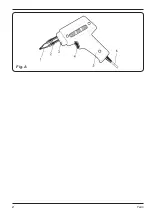
Страница 2: ...2 Ferm Fig A...
Страница 67: ...RU 67 Ferm 2 1 2 3 4 5 1 230 50 100 30 12 48 II 0 6 1 1 1 1 1 1 1 1 1 1 1 2 3 4 5 6 2 o o o o o o II...
Страница 68: ...RU 68 Ferm EN60335 1 1 5 2 3 4 3 4 12 48...
Страница 69: ...RU 69 Ferm 10 1 2 4 60 40...
Страница 70: ...RU 70 Ferm 60 40 5 H...
Страница 71: ...UA 71 Ferm 2 1 2 3 4 5 1 230 50 100 30 12 48 0 6 1 1 1 1 1 1 1 1...
Страница 72: ...UA 72 Ferm 1 1 1 2 3 4 5 6 2 EN60335 1...
Страница 73: ...UA 73 Ferm 1 5 2 3 4 3 4 12 48 10 1 2...
Страница 74: ...UA 74 Ferm 4 60 40 60 40 5...
Страница 75: ...EL 75 Ferm Ferm ET KO HTH IO 2 1 2 3 4 E 5 1 T 230 V 50 Hz 100 W 30 W 12s 48s II 0 6 kg 1 1 1 1 1 1 1 1 1 1...
Страница 76: ...EL 76 Ferm A 1 2 3 4 5 6 2 CE II H H N 60335 1...
Страница 77: ...EL 77 Ferm 1 5 mm2 3 A 4 3 4 12 48 10...
Страница 78: ...EL 78 Ferm 2 4 E 60 40 60 40 5...
Страница 79: ...EL 79 Ferm o...
Страница 80: ...80 Ferm...
Страница 81: ...81 Ferm...
Страница 82: ...82 Ferm...
Страница 84: ...www ferm com 1311 04 2013 Ferm B V...


