EN
4
Ferm
the appliance.
• Always fasten the nut tightly when attaching
the tip. This ensures a good electric
connection.
• Ventilate the place of work sufficiently in order
to take unwanted vapours quickly away from
melting material.
• During use, the soldering gun should be left
off.
• The mains power supply lead for the soldering
gun may only be replaced by a specialist
electrician.
• Use only original accessories which are
supplied or recommended by the
manufacturer.
Immediately unplug the soldering gun in case
of
• The soldering gun is overheated.
• Malfunction of the mainsplug, socket or
damaged cables.
• Broken switch.
• Smoke or smell caused by scorched
insulation.
Electrical safety
When using electric machines always observe the
safety regulations applicable in your country to
reduce the risk of fire, electric shock and personal
injury. Read the following safety instructions and
also the enclosed safety instructions.
Always check that the power supply
corresponds to the voltage on the rating
plate.
The machine is double insulated in
accordance with EN60335-1 therefore
no earth wire is required
replacing cables or plugs
Immediately throw away old cables or plugs when
they have been replaced by new ones. It is
dangerous to insert the plug of a loose cable in the
wall outlet.
Using extension cables
Only use an approved extension cable suitable for
the power input of the machine. The minimum
conductor size is 1.5 mm
2
. When using a cable
reel always unwind the reel completely.
3. Operating
Use this appliance only for work which
is included in the established operative
range.
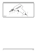
soldering gun
Fig. A
• Switch-on: press switch 4 and leave pressed.
Status indicator 3 lights up when the appliance
is switched on.
• Switch-off: release switch 4.
• The duration of the current supply determines
the heat of the solder (longer current supply =
higher solder temperature). While soldering,
do not keep the switch pressed for too long.
Determine the necessary duration for current
supply in practice through control of the
temperature of the solder. In order to achieve
a constant temperature, avoid constant
current for more than 12 seconds and cutoff
current of over 48 seconds. As soon as you
release the switch, the temperature of the
solder is automatically reduced. A subsequent
turning on of the switch ensures a fast
increase in temperature. Constant solder
temperature guarantees optimum solder
quality, avoids running the soldering tip at
temperatures which are too high and extends
the service life of the appliance.
soldering iron
• Plug in the soldering iron. Insert the plug into
the socket (with connection to earth). After a
short heating time, the soldering iron is ready
to use.
• Press the terminal pin strongly against the
parts which are to be soldered so that these
are heated. Ensure that the pin presses
against the greatest possible surface area of
the parts. Heat transfer is then at its greatest.
• Hold the tin solder wire at a safe distance so
that you do not burn your fingers. Then pass
the tin solder wire between the tip and the
parts which are to be soldered.
• If the parts have been heated sufficiently, melt
the tin solder and run it into the space between
the parts which are to be joined together.
• Remove the pin from the parts which are to be
joined together but without moving these and
wait until the joint has cooled down and set
(approx. 10 seconds.).
• If the joint has been soldered well, then you
will obtain a polished, shiny surface.
Содержание SGM1001
Страница 2: ...2 Ferm Fig A...
Страница 67: ...RU 67 Ferm 2 1 2 3 4 5 1 230 50 100 30 12 48 II 0 6 1 1 1 1 1 1 1 1 1 1 1 2 3 4 5 6 2 o o o o o o II...
Страница 68: ...RU 68 Ferm EN60335 1 1 5 2 3 4 3 4 12 48...
Страница 69: ...RU 69 Ferm 10 1 2 4 60 40...
Страница 70: ...RU 70 Ferm 60 40 5 H...
Страница 71: ...UA 71 Ferm 2 1 2 3 4 5 1 230 50 100 30 12 48 0 6 1 1 1 1 1 1 1 1...
Страница 72: ...UA 72 Ferm 1 1 1 2 3 4 5 6 2 EN60335 1...
Страница 73: ...UA 73 Ferm 1 5 2 3 4 3 4 12 48 10 1 2...
Страница 74: ...UA 74 Ferm 4 60 40 60 40 5...
Страница 75: ...EL 75 Ferm Ferm ET KO HTH IO 2 1 2 3 4 E 5 1 T 230 V 50 Hz 100 W 30 W 12s 48s II 0 6 kg 1 1 1 1 1 1 1 1 1 1...
Страница 76: ...EL 76 Ferm A 1 2 3 4 5 6 2 CE II H H N 60335 1...
Страница 77: ...EL 77 Ferm 1 5 mm2 3 A 4 3 4 12 48 10...
Страница 78: ...EL 78 Ferm 2 4 E 60 40 60 40 5...
Страница 79: ...EL 79 Ferm o...
Страница 80: ...80 Ferm...
Страница 81: ...81 Ferm...
Страница 82: ...82 Ferm...
Страница 84: ...www ferm com 1311 04 2013 Ferm B V...


