28
en
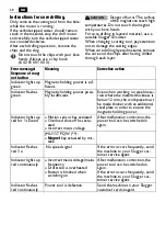
Instructions for core drilling.
Only remove the cutting tool from the hole
while the motor is running.
If the carbide tipped cutter should remain
stuck in the material, stop the drill motor
and carefully turn the carbide tipped cutter
out counterclockwise.
After each drilling operation, remove the
chips and the slug.
Do not touch the chips with your bare
hands. Always use a chip hook
(6 42 01 001 00 0).
Danger of burns! The surface
of the magnet can reach high
temperatures. Do not touch the magnet
with your bare hands.
For core drilling in layered material, use a
suitable Slugger ID cutter.
When changing a cutting tool, pay attention
not to damage the cutting edges.
When core drilling layered material, remove
the core and the chips after having drilled
through each layer.
CAUTION
Error message/
Response of mag-
net button
Meaning
Corrective action
Indicator lights up
green
Magnetic holding power is suf-
ficient.
Indicator flashes
green
Magnetic holding power possi-
bly insufficient.
Even when working on steel mate-
rials where the material thickness is
below 12 mm, the workpiece must
be made thicker with an additional
steel plate in order to ensure the
magnetic holding power.
Indicator lights up
red for 1 second
–
Motion sensor has actuated
–
Overload shut-off has actu-
ated
–
Incorrect mains voltage
After malfunction correction, the
power tool can be switched on
again.
JMU 137 PQW (**):
–
Magnet
key actuated by mis-
take
Indicator flashes
red 3 x
No speed signal
If the error occurs frequently, send
the machine to your Slugger cus-
tomer service agent.
Indicator lights up
red continuously
–
Incorrect mains voltage/mains
frequency
–
Drill stand is overheated
–
Button is blocked when
switching on
After malfunction correction, the
power tool can be switched on
again.
If the error occurs frequently, send
the machine to your Slugger cus-
tomer service agent.
Indicator flashes
red continuously
Power tool is defective.
Send the machine to your Slugger
customer service agent
Содержание JMU 137 PQW
Страница 1: ...JMU 137 QW 7 270 7 273 JMU 137 MQW 7 270 7 273 JMU 137 2 QW 7 270 7 273 JMU 137 PQW 7 270 ...
Страница 2: ...2 Instruction Manual Mode d emploi Instrucciones de uso en 3 fr 32 es 62 ...
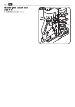
Страница 16: ...16 en Mounting the coolant hose figure 6 Connect the coolant hose 4 3 Fig 6 2 1 ...
Страница 76: ...76 es Montaje de la manguera de refrigerante Figura 6 Conecte la manguera de refrigerante 4 3 Fig 6 2 1 ...

