background image

5

en

Safety instructions.

When performing drilling that requires the 
use of a fluid, route the fluid away from the 
operator’s work area or use a collection sys-
tem. 

Such precautionary measures keep the 

operator’s work area dry and reduce the 
risk of electrical shock.

Operate the power tool by the insulated grip-
ping surfaces, when performing an opera-
tion where the cutting accessory may 
contact hidden wiring or its own cord. 

Con-

tact of a cutting accessory with a "live" wire 
may make exposed metal parts of the power 
tool "live" and could give the operator an 
electric shock. 

Wear hearing protection when drilling. 

Exposure to noise can cause hearing loss.

When the application tool jams, stop apply-
ing pressure and switch the power tool off. 

Check the cause of the jam and apply cor-
rective action to eliminate the cause of the 
jamming application tool. 

When restarting a core drill jammed in the 
workpiece, check that the application tool 
rotates freely before starting. 

If the applica-

tion tool is jammed, it may not start, may 
overload the power tool, or may cause the 
core drill to release from the workpiece.

When securing the drill stand with a vacuum 
plate to the workpiece, make sure that the 
surface is smooth, clean and non-porous. Do 
not secure the drill stand to laminated sur-
faces such as tiles and coated composite 
materials. 

 If the surface of the workpiece is 

not smooth, flat or well affixed, the vacuum 
plate may pull away from the workpiece.

Ensure there is sufficient vacuum level 
before and during drilling. 

If the vacuum 

level is insufficient, the vacuum plate may 
become detached from the workpiece. 

Never perform overhead and wall drilling 
when the machine is only fastened using the 
vacuum plate. 

If the vacuum is lost, the vac-

uum plate will release from the workpiece. 

When drilling through walls or ceilings, 
ensure to protect persons and the work area 
on the other side. 

The core bit may extend 

through the hole or the core may fall out on 
the other side.

Do not use this tool for overhead drilling 
with fluid supply. 

Fluids entering the power 

tool will increase the risk of electric shock. 

Special safety instructions.

Have the protective cable bushing replaced 
immediately when damaged. 

A defective 

protective cable bushing can lead to over-
heating of the machine.

Wear protective equipment. Depending on 
the application, wear face shield or safety 
goggles. Wear hearing protection. 

The 

safety glasses/goggles must be suitable to 
protect against the particles emitted from 
different operations. Continuous high expo-
sure to noise can lead to loss of hearing.

Do not touch the sharp edges of the core drill 
bit. 

Danger of injury.

To avoid injuries, check the core drill bits 
prior to starting the work. Use only undam-
aged core drill bits that are not deformed. 

Damaged or deformed core drill bits can 
cause serious injury.

Before putting into operation: Mount the 
chip guard to the machine. 

Always secure the machine with the 
supplied safety strap. 

Especially on 

inclined or uneven surfaces there is risk 
of unsecured machines tipping over.

When working overhead, beware of falling 
objects, such as cores or chips. 
When working overhead or on vertical sur-
faces, the coolant container must not be 
used. 

Use Slugger Cutting Paste instead. Liq-

uids penetrating your electric power tool 
maycause electric shock.

Avoid touching the drilled core that is auto-
matically ejected by the pilot pin when the 
working procedure is finished. 

Contact with 

the core when it is hot, or if it falls, can cause 
personal injuries.

Operate the power tool only from grounded 
contact sockets that comply with the speci-
fications. Do not use any connection cables 
that are damaged; use extension cables 
with a grounded contact that are checked at 
regular intervals. 

A ground conductor with-

out continuity can cause an electric shock.

Содержание JMU 137 PQW

Страница 1: ...JMU 137 QW 7 270 7 273 JMU 137 MQW 7 270 7 273 JMU 137 2 QW 7 270 7 273 JMU 137 PQW 7 270 ...

Страница 2: ...2 Instruction Manual Mode d emploi Instrucciones de uso en 3 fr 32 es 62 ...

Страница 3: ...s away while operating a power tool Distrac tions can cause you to lose control 2 Electrical safety a Power tool plugs must match the out let Never modify the plug in any way Do not use any adapter plugs with earthed grounded power tools Unmodified plugs and matching out lets will reduce risk of electric shock b Avoid body contact with earthed or grounded surfaces such as pipes radiators ranges an...

Страница 4: ... tool that cannot be controlled with the switch is dangerous and must be repaired c Disconnect the plug from the power source and or remove the battery pack if detachable from the power tool before making any adjustments changing accessories or storing power tools Such preventive safety measures reduce the risk of starting the power tool accidentally d Store idle power tools out of the reach of ch...

Страница 5: ...ugh walls or ceilings ensure to protect persons and the work area on the other side The core bit may extend through the hole or the core may fall out on the other side Do not use this tool for overhead drilling with fluid supply Fluids entering the power tool will increase the risk of electric shock Special safety instructions Have the protective cable bushing replaced immediately when damaged A d...

Страница 6: ...he power tool only in the case or packaging Before putting into operation check the power connection and the power plug for damage Always operate the power tool with together with a GFCI personal protection switch Before beginning to work always check the proper functioning of the GFCI personal pro tection switch see page 30 Handling hazardous dusts When working with power tools such as when grind...

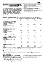
Страница 7: ...g of the power tool Oth erwise the extension cable and power tool are prone to electrical danger and the working efficiency is decreased CAUTION Sound emission JMU 137 QW JMU 137 MQW JMU 137 2 QW JMU 137 PQW A weighted emission pressure power level measured at the workplace LpA re 20 μPa in decibels 82 3 82 3 83 2 86 7 Measuring uncertainty KpA in decibels 5 5 5 3 Measured A weighted sound power l...

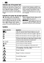
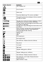
Страница 8: ...en in doubt please refer to the generator instruction specification guide Observe the operating instructions and the national regulations for the installation and operation of the AC generator Operating the power tool off power generators whose no load speed exceeds the voltage value on the type plate of the power tool is prohibited Symbols WARNING Symbol character Explanation Make sure to read th...

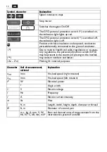
Страница 9: ...of a possible dangerous situation that could cause injury Worn out power tools and other electrotechnical and electrical products should be sorted separately for environmentally friendly recycling 1 gear 2 gear Tap size Steel Fluid supply open Fluid supply closed Start drill motor Rotation direction clockwise Stop motor Low speed High speed Magnetic holding power sufficient Magnetic holding power ...

Страница 10: ...nal protection switch GFCI may be present in the country of placing on the market may contain numbers and letters Ax Zx Marking for internal purposes Symbol character Explanation RESET TEST Character Unit of measurement national Explanation n0R min No load speed right rotation n0L min No load speed left rotation P W Electrical power Angle width U V Electric voltage f Hz Frequency I A Electric curr...

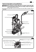
Страница 11: ...wn in this instruction manual will be included with your power tool WARNING Application tool Chip guard Tool holder Viseo Touch Pad Drill motor cable Coolant container Spoke handle Magnetic foot Clamping strap PRCD personal protection switch Fig 1 Switches the magnet On Off Starts the drill motor Rotation direction clockwise Speed reduction in steps Starts the drill motor in inch mode Rotation dir...

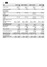
Страница 12: ...35 mm 1 2 in 1 3 8 in 12 mm 35 mm Drilling capacity in steel high speed steel HSS twist drill bit 5 8 in 16 mm 11 16 in 18 mm 5 8 in 16 mm 5 8 in 16 mm Tapped hole 9 16 4 in M14 9 16 4 in M14 9 16 4 in M14 9 16 4 in M14 Reamer diameter 5 8 in 16 mm 11 16 in 18 mm 5 8 in 16 mm 5 8 in 16 mm Counterboring diameter 1 1 4 in 31 mm 1 1 4 in 31 mm 1 1 4 in 31 mm 1 1 4 in 31 mm Weight according to EPTA Pr...

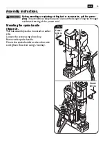
Страница 13: ...es out the danger of injuries through accidental starting of the power tool Mounting the spoke handle figure 3 The hub assembly can be mounted on either side Loosen the screw using a hex key Remove the spoke handle Mount the spoke handle on the other side and tighten the screw using a hex key WARNING 1 2 3 4 5 mm 3 16 in 5 mm 3 16 in Fig 3 ...

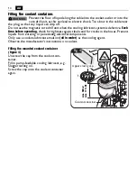
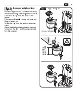
Страница 14: ...erating check for tightness against leaks and for cracks in the hoses Prevent liquids from entering or penetrating electrical components Only use a coolant lubricant emulsion oil in water as the cooling agent Observe the manufacturer s instructions on coolant Filling the mounted coolant container figure 4 Unscrew the cap from the coolant con tainer Fill in pump feedable cooling lubricant e g Slugg...

Страница 15: ... drill Unscrew the cap from the coolant con tainer Fill in pump feedable cooling lubricant e g Slugger cutting oil Screw the cap onto the coolant container again Insert the filled coolant container into the holder on the drill stand housing intended for this purpose 1 3 2 5 4 Coolant container Upper closing cap max 500 ml max 17 fl OZ Fig 5 ...

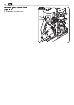
Страница 16: ...16 en Mounting the coolant hose figure 6 Connect the coolant hose 4 3 Fig 6 2 1 ...

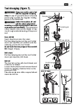
Страница 17: ...utter Pull the clamping sleeve of the tool holder down and insert the core drill bit with the centering pin into the tool holder Do not touch the sharp edges of the core drill bit Danger of injury Drill chuck Pull the clamping sleeve of the tool holder down and insert the drill chuck Drill bit The knurled nut has a left hand thread turn clockwise to release Loosen the knurled nut and remove the to...

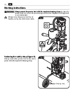
Страница 18: ... failure or when the power plug is pulled the magnetic holding power is not maintained Always carry the power tool by its handle not by the drill motor cable Fastening the safety strap figure 9 Always secure the power tool to the work piece with the supplied clamping strap WARNING Fig 8 Clamping strap Fig 9 ...

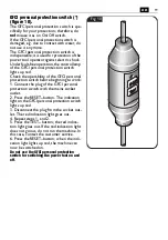
Страница 19: ...ty of the GFCI personal protection switch before beginning to work 1 Connect the plug of the GFCI personal protection switch with the mains socket outlet 2 Press the RESET button The indication light on the GFCI personal protection switch lights up red 3 Disconnect the plug from the socket out let The red indication light goes out 4 Repeat steps 1 and 2 5 Press the TEST button the red indica tion ...

Страница 20: ...power is sufficient and the machine can be operated with normal feed When the Magnet button on the control panel flashes the magnetic holding power possibly is insufficient and the machine must be operated with reduced feed When working non metal materials suit able manufacturer fastening devices such as vacuum plates or pipe drilling devices which are available as accessories must be used Observe...

Страница 21: ...n be operated with normal feed When the Magnet button on the control panel flashes the magnetic holding power possibly is insufficient and the machine must be operated with reduced feed When working non magnetic materials suitable FEIN fastening devices such as vac uum plates or pipe drilling devices which are available as accessories must be used Observe the corresponding operating instructions f...

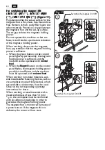
Страница 22: ...off the magnetization JMU 137 PQW figure 13 Slide the handle lever sleeve upward Set the hand lever to the 0 position The handle lever sleeve automatically retracts back to the starting position Fig 13 100 30 0 1 3 2 0 ...

Страница 23: ... two fastening levers To move the fastening levers over each other pull a fastening lever outward and then turn the fastening lever in 45 steps Loosen both fastening levers with the other hand Adjust the desired stroke range Tighten both fastening levers again CAUTION 1 2 2 3 1 4 4 2 2 1 3 4 4 2 2 Fig 14 ...

Страница 24: ...pen the ventilation first and then turn the flow valve to the posi tion shown For switching off or when working overhead deactivate the cooling lubricant flow Shut the ventilation and turn the flow valve to the posi tion shown When working overhead use a cooling lubricant paste from Slugger Fig 15 1 2 Ventilation ...

Страница 25: ...illing with small drill bit diameters Fig 16 Drilling capacity in steel TCT high speed steel core drill bits Drilling capacity in steel high speed steel HSS twist drill bit Tapped hole JMU 137 QW JMU 137 2 QW JMU 137 PQW 1 Gear 1 2 in 1 3 8 in 12 mm 35 mm 1 4 in 5 8 in 6 mm 16 mm 3 8 in 9 16 in M5 M14 JMU 137 MQW 1 Gear 1 2 in 1 3 8 in 12 mm 35 mm 3 8 in 11 16 in 10 mm 18 mm 3 8 in 9 16 in M5 M14 ...

Страница 26: ...ym bol To increase the speed press the sym bol To stop the drill motor press the symbol Do not stop the drill motor during the drill ing procedure To start the drill motor with counterclock wise rotation press the button with the symbol The drill motor will run as long as the button is pressed When the power supply is disconnected while the motor is running a protective cir cuit prevents automatic...

Страница 27: ...akage of the application tool and loss of the magnetic holding power To generate feed turn the spoke handle manually while the drill motor is switched on The scale can be used with inch or with cm graduation Mounting the spoke handle is described under Mounting the spoke handle cm inch 1 inch cm 3 2 Fig 18 ...

Страница 28: ...agnetic holding power is suf ficient Indicator flashes green Magnetic holding power possi bly insufficient Even when working on steel mate rials where the material thickness is below 12 mm the workpiece must be made thicker with an additional steel plate in order to ensure the magnetic holding power Indicator lights up red for 1 second Motion sensor has actuated Overload shut off has actu ated Inc...

Страница 29: ... tools coolant container contact protector Drill motor guide figure 19 After several hours of operation the play in the drill motor guide can increase As a conse quence the drill motor can glide alongside the drill motor guide by itself Malfunctions are possible in machine operation In this case retighten all fastening screws of the drill motor guide correspondingly so that the drill motor can eas...

Страница 30: ...st in the air such as when working metals this dust can settle in the interior of the power tool This can impair the total insulation of the power tool Therefore regularly blow out the interior of the power tool from outside via the ventilation openings with dry oil free compressed air always wear eye protection when doing this Do not attempt to clean clogged or dirty ventilation openings of the p...

Страница 31: ...31 en Provided accessories figure 20 Drift Power tool carrying case Tool holder Centering pin Chip hook Clamping strap Chip guard JMU 137 MQW JMU 137 MQW Fig 20 ...

Страница 32: ... la zone de travail a Maintenir la zone de travail propre et bien éclairée Les zones en désordre ou sombres sont propices aux acci dents b Ne pas faire fonctionner les outils électriques en atmosphère explosive par exemple en présence de liquides inflammables de gaz ou de poussiè res Les outils électriques produisent des étincelles qui peuvent enflammer les poussières ou les fumées c Maintenir les...

Страница 33: ...e dans des situations inattendues f S habiller de manière adaptée Ne pas porter de vêtements amples ou de bijoux Garder les cheveux et les vête ments à distance des parties en mou vement Des vêtements amples des bijoux ou les cheveux longs peuvent être pris dans des parties en mouve ment g Si des dispositifs sont fournis pour le raccordement d équipements pour l extraction et la récupération des p...

Страница 34: ...ollecteur de fluide De telles précautions permettent de garder sèche la zone de travail et de réduire les risques d électrocution Lors de l exécution de travaux pendant les quels l outil de coupe pourrait entrer en contact avec des conducteurs cachés ou avec son propre câble d alimentation n uti lisez l outil électrique qu en le tenant par les poignées isolées Lorsqu un outil coupant entre en cont...

Страница 35: ...er à toujours se protéger contre les objets tombants tels que carottes et copeaux Effectuez les travaux sur les éléments de construction verticaux ou au dessus de la tête sans utiliser le réservoir du liquide de refroidissement Utilisez un spray refroidis sant Les liquides qui entreraient dans l outil électrique peuvent causer un choc électri que Éviter de toucher la carotte qui est automa tiqueme...

Страница 36: ... matériaux contenant de l amiante peintures contenant du plomb certains bois tels que le bois de chêne et de hêtre minéraux et métal les particules de silicate contenues dans les briques le béton et autres matériaux contenant de la roche les solvants contenus dans les vernis et peintures l arsenic le chrome et d autres lasures produits pour la lutte contre les vermines sur la coque de bateaux et d...

Страница 37: ...e lieu de travail LpA re 20 μPa en décibel 82 3 82 3 83 2 86 7 Incertitude KpA en décibel 5 5 5 3 Mesure réelle A du niveau d intensité acoustique pondé ré LwA re 1 pW en décibel 93 2 93 2 94 2 97 7 Incertitude KwA en décibel 5 5 5 3 Mesure réelle C du niveau max de pression acoustique sur le lieu de travail LpCpeak en décibel 95 9 95 9 96 8 101 2 Incertitude KpCpeak en décibel 5 5 5 3 valeur de v...

Страница 38: ... cas de doute s informer sur le groupe électrogène utilisé Respectez la notice d utilisation et les dispo sitions nationales relatives à l installation et l utilisation du groupe électrogène Il est interdit de faire fonctionner l outil électrique sur des générateurs de courant dont la tension à vide dépasse la valeur de tension indiquée sur la plaque signalétique de l outil électrique Symboles AVE...

Страница 39: ...aîner de graves blessures ou la mort Cette indication met en garde contre une situation poten tiellement dangereuse qui peut entraîner des blessures Trier les outils électriques ainsi que tout autre produit électrotechnique et électrique et les déposer à un centre de recyclage respectant les directives relatives à la protection de l environnement 1ère vitesse 2e vitesse Taraud Acier Alimentation e...

Страница 40: ...aux dispositions relatives à la protection des travailleurs ou aux dispositions légales dans les pays de mise sur le mar ché peut contenir des chiffres ou des lettres Ax Zx Marquage interne Symbole signe Explication RESET TEST Signe Unité nationale Explication n0R tr min Vitesse à vide rotation vers la droite n0L tr min Vitesse à vide rotation vers la gauche P W Unité de mesure pour la puissance é...

Страница 41: ...isation soit fournie avec l outil électrique AVERTISSEMENT Outil de travail Dispositif anti copeaux Porte outil Viseo Touch Pad Câble de moteur de carottage Réservoir du produit de refroidissement Croisillon Embase électromagnétique Sangle de serrage Interrupteur de protection individuelle PRCD Fig 1 Activer désactiver l aimant Démarrer le moteur de carottage Sens de rotation vers la droite Réduir...

Страница 42: ...n 1 3 8 in 12 mm 35 mm 1 2 in 1 3 8 in 12 mm 35 mm 1 2 in 1 3 8 in 12 mm 35 mm Diamètre de perçage acier acier rapide foret hélicoïdal 5 8 in 16 mm 11 16 in 18 mm 5 8 in 16 mm 5 8 in 16 mm Alésage 9 16 in M14 9 16 in M14 9 16 in M14 9 16 in M14 Diamètre alésoir 5 8 in 16 mm 11 16 in 18 mm 5 8 in 16 mm 5 8 in 16 mm Diamètre lamage 1 1 4 in 31 mm 1 1 4 in 31 mm 1 1 4 in 31 mm 1 1 4 in 31 mm Poids su...

Страница 43: ...n danger de blessure causé par un démarrage non intentionné de l outil électrique Montage du croisillon figure 3 Le croisillon peut être monté des deux côtés Desserrez la vis à l aide d une clé mâle pour vis à six pans creux Retirez le croisillon Introduisez le croisillon de l autre côté et serrezh la vis à l aide d une clé pour vis à six pans creux AVERTISSEMENT 1 2 3 4 5 mm 3 16 in 5 mm 3 16 in ...

Страница 44: ...flexibles présentent des fissures Éviter la pénétration de liquide dans les éléments électriques N utilisez comme réfrigérant qu une émulsion de lubrifiant réfrigérant mélange huile eau Tenez compte des instructions du fabricant du produit Remplissage du réservoir du liquide de refroidissement monté figure 4 Dévissez le capuchon du réservoir du liquide de refroidissement Remplissez d un liquide de...

Страница 45: ... réservoir du liquide de refroidissement Remplissez d un liquide de refroidissement pouvant être pompé par ex huile de coupe Slugger Revissez le capuchon du réservoir du liquide de refroidissement Montez le réservoir du liquide de refroidis sement rempli dans le support prévu du support de perçage 1 3 2 5 4 Réservoir du produit de refroidissement Capuchon supérieur max 500 ml max 17 fl OZ Fig 5 ...

Страница 46: ...46 fr Montage du tuyau du liquide de refroidissement figure 6 Connectez le tuyau du liquide de refroidis sement 4 3 Fig 6 2 1 ...

Страница 47: ... la douille de serrage du porte outil vers le bas et introduisez la fraise à carotter avec la tige de centrage dans le porte outil Ne pas toucher les bords aigus de la fraise à carotter Danger de blessure Mandrin de perçage Tirez la douille de serrage du porte outil vers le bas et introduisez le mandrin de per çage Foret hélicoïdal L écrou de blocage a un filet à gauche tour ner vers la droite pou...

Страница 48: ...action magnétique n est plus active lors d une panne de courant ou lorsque l appareil est débranché Porter l outil par la poignée et ne pas par le câble du moteur de carottage Montage de la sangle de serrage figure 9 Bloquez la machine sur la pièce à l aide de la sangle de serrage AVERTISSEMENT Fig 8 Sangle de serrage Fig 9 ...

Страница 49: ... le travail vérifiez le fonctionnement de l interrupteur de protec tion personnelle 1 Branchez la fiche de l interrupteur de pro tection personnelle à la prise de courant 2 Appuyez sur la touche RESET Le témoin de contrôle de l interrupteur de protection personnelle s allume en rouge 3 Retirez la fiche de la prise de courant Le voyant lumineux rouge s éteint 4 Répétez les étapes 1 et 2 5 Appuyez s...

Страница 50: ...gnétique est suffisante et la machine peut être utilisée avec avance normale Si la touche aimant du panneau de com mande clignote c est que la force magné tique n est éventuellement pas suffisante et la machine doit être utilisée avec un effort d avance réduit Pour les travaux sur les matériaux non fer reux utilisez des dispositifs de fixation appropriés du fabricant disponibles comme accessoires ...

Страница 51: ...te et la machine peut être utilisée avec avance normale Si la touche aimant du panneau de com mande clignote c est que la force magné tique n est éventuellement pas suffisante et la machine doit être utilisée avec un effort d avance réduit Pour les travaux sur les matériaux non magnétiques utiliser des dispositifs de fixa tion FEIN appropriés disponibles comme accessoires tels que par ex plaque à ...

Страница 52: ...tion JMU 137 PQW figure 13 Pousser la douille du levier manuel vers le haut Mettre le levier manuel sur la position 0 La douille sur le levier manuel se remet automatiquement dans la position d origine Fig 13 100 30 0 1 3 2 0 ...

Страница 53: ...sserrez les deux leviers de fixation Pour pouvoir bouger les leviers de fixation superposés tirer le levier de fixation vers l avant et le tourner en pas de 45 Desserrez les deux leviers de fixation de l autre main Réglez la plage de course souhaitée Resserrez les deux leviers de fixation ATTENTION 1 2 2 3 1 4 4 2 2 1 3 4 4 2 2 Fig 14 ...

Страница 54: ...e traversée dans la position indiquée sur la figure Pour arrêter ou pour les travaux effectués au dessus de la tête arrêtez le débit du liquide de refroidisse ment Fermez la purge d air et tour nez la soupape de traversée dans la position indiquée sur la figure Pour les travaux effectués au dessus de la tête utilisez une pâte de refroidissement de Slugger Fig 15 1 2 Aération ...

Страница 55: ...approprié pour le perçage de petits diamè tres Fig 16 Diamètre de perçage acier carbure acier rapide carotteur Diamètre de perçage acier acier rapide foret hélicoïdal Alésage JMU 137 QW JMU 137 2 QW JMU 137 PQW 1ère vitesse 1 2 in 1 3 8 in 12 mm 35 mm 1 4 in 5 8 in 6 mm 16 mm 3 8 in 9 16 in M5 M14 JMU 137 MQW 1ère vitesse 1 2 in 1 3 8 in 12 mm 35 mm 3 8 in 11 16 in 10 mm 18 mm 3 8 in 9 16 in M5 M1...

Страница 56: ...tou che Pour augmenter la vitesse appuyer sur la touche Pour arrêter le moteur de carottage appuyez sur la touche N arrêtez pas le moteur de carottage durant le processus de perçage Pour démarrer le moteur en rotation gau che appuyer sur la touche portant le sym bole Le moteur de carottage reste en marche tant que la touche est appuyée Lorsque l alimentation en courant électrique est interrompue a...

Страница 57: ...r une rupture de l accessoire et une perte de la force d attrac tion magnétique Tournez le croisillon manuellement le moteur mis en marche pour générer l avance Vous pouvez utiliser l échelle de graduation avec inch ou avec cm Le montage du croisillon est décrit dans le chapitre Montage du croisillon cm inch 1 inch cm 3 2 Fig 18 ...

Страница 58: ...e voyant s allume vert Force d attraction magnétique suffisante Le voyant clignote vert Force d attraction magnétique éventuellement insuffisante Afin de garantir la force d attraction magnétique sur des matériaux en acier d une épaisseur inférieure à 12 mm ajouter sous la pièce à travailler par une plaque supplémentaire en acier Voyant s allume rouge pendant 1 seconde Le détecteur de mouvement a ...

Страница 59: ...de travail réservoir de liquide de refroidissement protège mains Guidage du moteur de carottage figure 19 Au bout de quelques heures de service le jeu dans le moteur de carottage pourrait augmen ter Le moteur de carottage pourrait alors glisser le long du guidage Des perturbations de fonctionnement sont possibles Dans un tel cas resserrez de manière appropriée toutes les vis de fixation du guidage...

Страница 60: ...ilisation de l outil p ex lors du traitement de métaux cette poussière peut se déposer à l intérieur de l outil électrique La double isolation de l outil électrique peut ainsi être endommagée Soufflez alors régu lièrement de l extérieur de l air comprimé sec exempt d huile dans l intérieur de l outil électrique à travers les ouïes de ventilation utilisez toujours une protection oculaire N essayez ...

Страница 61: ...61 fr Accessoires fournis figure 20 Chasse cône Coffret Porte outil Crochet à copeaux Sangle de serrage Dispositif anti copeaux Goupille de centrage longue JMU 137 MQW JMU 137 MQW Fig 20 ...

Страница 62: ...ales de seguridad 1 Seguridad del puesto de trabajo a Mantenga limpio y bien iluminado su puesto de trabajo El desorden o una iluminación deficiente en las áreas de trabajo pueden provocar accidentes b No utilice la herramienta eléctrica en un entorno con peligro de explosión en el que se encuentren combustibles líquidos gases o material en polvo Las herramientas eléctricas producen chis pas que p...

Страница 63: ...o lla ves fijas antes de conectar la herra mienta eléctrica Una herramienta de ajuste o llave fija colocada en una pieza rotante puede producir lesiones al poner a funcionar la herramienta eléc trica e Evite posturas arriesgadas Trabaje sobre una base firme y mantenga el equilibrio en todo momento Ello le permitirá controlar mejor la herra mienta eléctrica en caso de presentarse una situación ines...

Страница 64: ...ta aplicar líquido al taladrar cuide que el líquido rebosante sea desviado fuera de la zona de trabajo o use un dispositivo apropiado para recoger líquidos Estas medi das de precaución evitan que se moje el área de trabajo y reducen el riesgo de electrocu ción Use la herramienta eléctrica sujetándola por las áreas de agarre aisladas al realizar tra bajos en los que el útil de corte pueda tocar lín...

Страница 65: ...ito de refrigerante si tuviese que mantener el aparato en posición vertical o por encima de la cabeza al traba jar las piezas Emplee un spray de refrigera ción en estos casos La penetración de líquido en la herramienta eléctrica puede ocasionar una descarga eléctrica Evite el contacto con el núcleo de perfora ción que el perno de centrado expulsa auto máticamente al finalizar el trabajo Al ser gol...

Страница 66: ... cuyo polvo producido al tra bajar puede ser nocivo para la salud Amianto y materiales que contengan amianto Pinturas que contengan plomo ciertos tipos de madera como p ej haya encino y roble Minerales y metales Partículas de sílice de ladrillo concreto y demás materiales que contengan mineral Los solventes que contienen ciertas pin turas Arsénico cromo y otros conservadores de la madera Materiale...

Страница 67: ...ra bajo en decibelios 82 3 82 3 83 2 86 7 Inseguridad KpA en decibelios 5 5 5 3 Nivel de potencia acústica LwA re 1 pW medido con filtro A en decibelios 93 2 93 2 94 2 97 7 Inseguridad KwA en decibelios 5 5 5 3 Valor pico del nivel de presión sonora LpCpeak medido con fil tro C en el puesto de trabajo en decibelios 95 9 95 9 96 8 101 2 Inseguridad KpCpeak en decibelios 5 5 5 3 Promedio de vibracio...

Страница 68: ...stablecido en dicha norma En caso de duda consulte los datos del grupo utilizado por Ud Tenga en cuenta en ello las instrucciones de uso y la normativa nacional sobre la instala ción y el funcionamiento del grupo electró geno de alterna Esta prohibido conectar la herramienta eléctrica a generadores de corriente cuya tensión en vacío sea superior a la tensión indicada en la placa de características...

Страница 69: ... una situación peligrosa que puede comportar lesiones graves o mortales Este símbolo advierte sobre una situación peligrosa en la que pudiera lesionarse Acumular por separado las herramientas eléctricas y demás productos electrotécnicos y eléctricos inservibles y someterlos a un reciclaje ecológico 1 velocidad 2 velocidad Macho de roscar Acero Paso de líquido cerrado Paso de líquido abierto Arranq...

Страница 70: ... PRCD puede exis tir si lo exigen las disposiciones de previsión laboral nacio nales o las normativas legales del país del distribuidor original Puede contener cifras o letras Ax Zx Identificación para fines internos Símbolo Definición RESET TEST Símbolo Unidad nacional Definición n0R rpm Revoluciones en vacío giro a derechas n0L rpm Revoluciones en vacío giro a izquierdas P W Unidad de medida de ...

Страница 71: ...talidad al material descrito o mostrado en estas instrucciones de servicio ADVERTENCIA Útil Guarda contra contacto Portaútiles Viseo Touch Pad Línea del motor de taladrar Depósito de refrigerante Palanca Base magnética Cinta tensora Interruptor de protección personal PRCD Fig 1 Conexión y desconexión el imán Arranque del motor de taladrar Sentido de giro a derechas Reducción escalonada de la veloc...

Страница 72: ...8 in 12 mm 35 mm 1 2 in 1 3 8 in 12 mm 35 mm 1 2 in 1 3 8 in 12 mm 35 mm Diámetro de taladro en acero acero de corte de alto rendimiento broca helicoidal 5 8 in 16 mm 11 16 in 18 mm 5 8 in 16 mm 5 8 in 16 mm Taladro para roscar 9 16 in M14 9 16 in M14 9 16 in M14 9 16 in M14 Diámetro de rima 5 8 in 16 mm 11 16 in 18 mm 5 8 in 16 mm 5 8 in 16 mm Diámetro avellanar 1 1 4 in 31 mm 1 1 4 in 31 mm 1 1 ...

Страница 73: ...ccidentes que pudieran presentarse en caso de una puesta en marcha involuntaria Montaje de la palanca Figura 3 Es posible acoplar la palanca al lado que Ud prefiera Afloje el tornillo con una llave Allen Retire la palanca Acople la palanca en el otro lado y apriete firmemente el tornillo con una llave allen ADVERTENCIA 1 2 3 4 5 mm 3 16 in 5 mm 3 16 in Fig 3 ...

Страница 74: ...la hermeticidad y la existencia de posibles fisuras en las mangueras Evite que penetren líquidos en las piezas eléctricas Como refrigerante utilice exclusivamente taladrina emulsión de aceite en agua Preste atención a las instrucciones del fabricante del agente refrigerante Llenado del depósito de refrigerante montado Figura 4 Desenrosque la tapa de cierre del depósito de refrigerante Llene líquid...

Страница 75: ... cierre del depósito de refrigerante Llene líquido lubricante refrigerante apro piado para ser bombeado p ej aceite de corte Slugger Vuelva a cerrar el tapón del depósito de refrigerante Una vez llenado monte el depósito de refri gerante en el soporte previsto para tal fin en la carcasa del soporte de taladrar 1 3 2 5 4 Depósito de refrigerante Tapón superior max 500 ml max 17 fl OZ Fig 5 ...

Страница 76: ...76 es Montaje de la manguera de refrigerante Figura 6 Conecte la manguera de refrigerante 4 3 Fig 6 2 1 ...

Страница 77: ...corona per foradora Jale hacia abajo el casquillo tensor del porta útiles y aloje en el mismo la corona perfora dora junto con el perno de centrado No toque los filos cortantes de la corona per foradora Podría lesionarse Broquero Jale hacia abajo el casquillo tensor del porta útiles y aloje en el mismo el broquero Broca La tuerca de bloqueo es de rosca a izquier das girarla a derechas para aflojar...

Страница 78: ...eción magnética se anula en caso de un corte de luz o al sacar la clavija de la red Siempre transporte la máquina sujetán dola por la agarradera y no por el cable del motor Sujeción de la cinta tensora Figura 9 Siempre amarre la máquina a la pieza de tra bajo con la cinta tensora suministrada ADVERTENCIA Fig 8 Cinta tensora Fig 9 ...

Страница 79: ...na de color rojo Antes de comenzar a trabajar compruebe el funcionamiento correcto del interruptor de protección personal 1 Conecte el enchufe del interruptor de protección personal a la red 2 Accione el botón RESET El piloto del interruptor de protección personal se enciende de color rojo 3 Saque el enchufe de la toma de corriente El piloto rojo se apaga 4 Repita los pasos 1 y 2 5 Presione el bot...

Страница 80: ...do se enciende permanentemente la máquina puede utilizarse con avance nor mal Si la tecla Magnet del panel de mando parpadea es probable que sea insuficiente la fuerza magnética de sujeción y es nece sario operar la máquina con fuerza de avance reducida Al trabajar en materiales no metálicos es necesario usar los accesorios de sujeción apropiados del fabricante como p ej la placa de vacío o el dis...

Страница 81: ...la máquina puede utilizarse con avance nor mal Si la tecla Magnet del panel de mando parpadea es probable que sea insuficiente la fuerza magnética de sujeción y es nece sario operar la máquina con fuerza de avance reducida Al trabajar en materiales no magnéticos es necesario usar dispositivos de sujeción FEIN apropiados adquiribles como accesorio como p ej la placa de vacío o el dispositivo para t...

Страница 82: ... magnetización JMU 137 PQW Figura 13 Desplace hacia arriba el casquillo de la palanca Coloque la palanca en la posición de 0 El casquillo de la palanca regresa automática mente a la posición de partida Fig 13 100 30 0 1 3 2 0 ...

Страница 83: ...el motor de taladrar Para poder girar las palancas de sujeción de manera que no se crucen jale hacia afuera la palanca de sujeción y vaya girándola en pasos de 45 Afloje ambas palancas de sujeción con la otra mano Ajuste el recorrido deseado Vuelva a apretar ambas palancas de sujeción ATENCIÓN 1 2 2 3 1 4 4 2 2 1 3 4 4 2 2 Fig 14 ...

Страница 84: ...dor y gire la llave de paso a la posición mostrada Al desconectar el aparato o realizar trabajos por encima de la cabeza corte el paso de refrigerante Cierre el purgador y gire la llave de paso a la posición mostrada Al realizar trabajos por encima de la cabeza emplee pasta refrigerante Slugger Fig 15 1 2 Purgado ...

Страница 85: ...izar taladros peque ños Fig 16 Diámetro de taladro acero metal duro acero de corte rápido de alto rendimiento corona perforadora Diámetro de taladro en acero acero de corte de alto rendimiento broca helicoidal Taladro para roscar JMU 137 QW JMU 137 2 QW JMU 137 PQW 1ª velo cidad 1 2 in 1 3 8 in 12 mm 35 mm 1 4 in 5 8 in 6 mm 16 mm 3 8 in 9 16 in M5 M14 JMU 137 MQW 1ª velo cidad 1 2 in 1 3 8 in 12 ...

Страница 86: ...ucir la velocidad pulse la tecla Para aumentar la velocidad pulse la tecla Para detener el motor de taladrar pulse la tecla No detenga el motor de taladrar durante la perforación Para arrancar el motor de taladrar con giro a izquierdas pulse la tecla con el símbolo El motor de taladrar funciona mien tras se tenga pulsada la tecla Si la alimentación se corta con el motor en marcha un circuito de pr...

Страница 87: ...a puede provocar la rotura del útil y hacer que se desprenda la base magnética Avance el motor de taladrar conectado girando a mano la palanca La escala la puede Ud utilizar con la unidad de medida en inch o en cm El montaje de la palanca se describe en el capítulo Montaje de la palanca cm inch 1 inch cm 3 2 Fig 18 ...

Страница 88: ...cador verde encendido La fuerza de sujeción magnética es suficiente Indicador verde parpadea La fuerza de sujeción magnética puede ser insuficiente Al trabajar en materiales de acero de un grosor inferior a 12 mm es necesario reforzarlos con una placa de acero adicional para asegurar que sea suficiente la fuerza magnética de sujeción El indicador se enciende de color rojo durante 1 segundo Se ha a...

Страница 89: ...tra contacto Guía del motor de taladrar figura 19 Con el uso de la máquina puede ir aumentando la holgura en la guía del motor de taladrar Esto puede dar lugar a que el taladro se deslice por sí mismo a lo largo de la guía del motor de taladrar Esto puede dificultar el trabajo con la máquina En ese caso apriete con cuidado todos los tornillos de ajuste de la guía del motor de taladrar de forma que...

Страница 90: ...conductor p ej al trabajar metales puede que este material llegue a depositarse en el interior de la herramienta eléctrica Ello puede mermar la eficacia del aislamiento de protección de la herramienta eléctrica Por ello sople con regularidad desde afuera por las rejillas de refrigeración el interior de la herramienta eléctrica con aire comprimido seco y exento de aceite utilizando en ello siempre ...

Страница 91: ...ccesorios incluidos en el suministro figura 20 Cuña extractora Maletín de Transporte Portaútiles Perno de centrado largo Gancho para virutas Cinta tensora Guarda contra contacto JMU 137 MQW JMU 137 MQW Fig 20 ...

Страница 92: ...05 www feinus com Canada FEIN Canadian Power Tool Company 323 Traders Boulevard East Mississauga Ontario L4Z 2E5 www fein ca FEIN Service FEIN Power Tools Inc 2735 Hickory Grove Road Davenport IA 52804 magdrillrepair feinus com Headquarter C E Fein GmbH Hans Fein Straße 81 D 73529 Schwäbisch Gmünd Bargau www fein com ...

Отзывы: