


16
Valor
®
Light Bar
Federal Signal
www.fedsig.com
Preparing the Valor for Installation
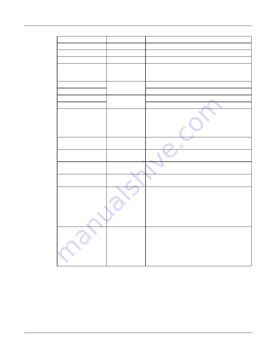
Table 5 Control wires from the Serial Interface Module
Light Bar Controls
Wire Color
Description
Mode 1
Blue
Lowest priority
Mode 2
Blue/White
Overrides Mode 1.
Mode 3
Black/Red
Overrides Modes 1 and 2.
Steady Burn
(HotFoot only)
Red/White
One or more LEDs steadily burn when 12 Vdc
is applied to the control wire for a Mode and the
control wire for Steady Burn.
Front Cutoff
Green/White
Turns off the front of the light bar.
Front Enable
Turns on the front of the light bar.
Rear Cutoff
Orange/Black
Turns off the rear of the light bar.
Rear Enable
Turns on the rear of the light bar.
Low Power
White/Black/Red Dims the lights approximately 50 percent to
prevent blinding approaching drivers. Low Power
is only available in Modes 1 and 2 and is disabled
when switched to another flash pattern, including
Mode 3 and Intersection.
Flash Takedown/Alley Red/Black
Flashes the alley and takedown lights in Modes 1,
2, or 3.
Left Alley
Green/Black
Turns on left alley lights. Overrides the Flash
Takedown/Alley lights.
Right Alley
Orange/Red
Turns on right alley lights. Overrides the Flash
Takedown/Alley lights.
Takedown
White/Black
Provides white light to the front. Overrides Flash
Takedown/Alley lights and front cutoff.
Intersection
(SW2 Switch 3 in the
up position)
Scene Light, Left
(SW2 Switch 3 in the
down position)
Blue/Black
Typically a high activity pattern. Overrides all three
priority modes. Scene Light, Left is unavailable.
Applying 12 Vdc to the Scene Light, Left wire turns
on the left half of the light bar (only for Valor and
Valor). Intersection is unavailable.
Light Bar Test Pattern
(SW2 Switch 3 in the
up position)
Scene Light, Right
(SW2 Switch 3 in the
down position)
Black/White/Red
Flashes the LEDs sequentially and then flashes
the takedown and alley lights. Scene Light, Right is
unavailable.
Applying 12 Vdc to the Scene Light, Right wire
turns on right half of the light bar. Light Bar Test
Pattern is unavailable.


