background image

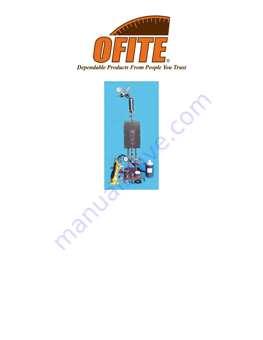
Permeability Plugging Tester - P.P.T.

4,000 PSI (27,600 kPa) - 500°F (260°C)

Part No. 171-84 (115V)

Part No. 171-84-01 (230V)

Instruction Manual

Updated 1/4/2017

Ver. 3.0

OFI Testing Equipment, Inc.

11302 Steeplecrest Dr. · Houston, Texas · 77065 · U.S.A.

Tele: 832.320.7300  · Fax: 713.880.9886 · www.ofite.com

©

Copyright OFITE 2013

Summary of Contents for PPT

Page 1: ...00 kPa 500 F 260 C Part No 171 84 115V Part No 171 84 01 230V Instruction Manual Updated 1 4 2017 Ver 3 0 OFI Testing Equipment Inc 11302 Steeplecrest Dr Houston Texas 77065 U S A Tele 832 320 7300 Fa...

Page 2: ...x 713 880 9886 www ofite com 1 Intro 2 Description 2 Specifications 3 Components 4 Safety 6 Operation 9 Preparation 9 Loading the Cell 10 Test Procedure 15 Disassembly 16 Reporting Data 18 Calculation...

Page 3: ...scribed outlet cap for the ceramic filter disks The outlet end of the cell has a 6 35 mm deeper recess than a standard cell to allow for the ceramic disk as a filter medium The end cap used with the 6...

Page 4: ...www ofite com 3 Specifications Weight 61 lbs 27 7 kg Dimensions 15 25 42 38 1 63 5 106 7 cm Shipping Weight 90 lbs 40 8 kg Shipping Dimensions 30 18 17 76 2 45 7 43 2 cm 800W Heater 316 Stainless Ste...

Page 5: ...70 72 Spacer for Filter Paper 171 84 03 Strap Wrench 171 85 Cell Assembly 500 mL Double Cap Complete 171 85 002 Cell Cap Inlet 171 86 1 Cell Body 171 88 1 Cell Cap Outlet Scribed 171 88 2 Cell Cap wit...

Page 6: ...or Airco Regulator 143 02 13 O ring for Puncture Pin Holder Assembly CO2 Cartridge Qty 2 143 02 14 O ring for Puncture Pin Assembly Qty 2 143 05 CO2 Bulbs EZ Puncture PKG 10 UN 1013 Qty 30 143 07 Repa...

Page 7: ...ize the back pressure receiver Never connect it to compressed air oxygen or other non recommended gas If nitrogen is used it must be supplied in an approved nitrogen gas cylinder and it must be secure...

Page 8: ...indicate an elec trical repair job may be required Always disconnect the power cables before attempting any repair 8 The filtration cell assembly is a pressure vessel and these safety precau tions sh...

Page 9: ...ll Rest Plunger 171 94 Inlet Valve Stem 171 90 08 Gauge 171 41 Graduated Cylinder 153 14 Inlet Valve 171 98 Hydraulic Pump 171 96 Thermometer 154 20 Spacer 170 72 Allen Wrench 170 27 T Handle 171 95 H...

Page 10: ...ture should read 10 F 6 C above the desired test temperature If it is not adjust the thermostat 4 Before using the ceramic disk soak it for at least 10 minutes in base fluid Use water for freshwater b...

Page 11: ...Grease to the threads on the cell caps 3 Position the cell upright with the inlet or shallow recess facing upwards Check the o ring recess to make sure it is clean Carefully insert an o ring 170 13 3...

Page 12: ...surizing hose with the 2 0 cm ball valve and quick connect fitting to the inlet valve stem assembly Make sure the quick connect fittings are completely attached Pull down hard on the ring on the femal...

Page 13: ...ody rotation while installing the outlet end cap If you are using filter paper instead of a ceramic disk use the provided screened cell cap to prevent tearing The screened cap is 2 thicker to account...

Page 14: ...onto the top of the valve stem assembly Be careful to not rotate the valve assembly Lock the receiver in place with the safety pin and lanyard Be sure that the pin is all the way in The outlet drain v...

Page 15: ...s heating the pressure inside will rise due to the thermal expansion Use the pump to release hydraulic oil and prevent over pressurization Maintain the pressure on the fluid until the desired tem pera...

Page 16: ...pressure and test temperature within 5 F 3 C 3 During filtration collection the pressure in the cell will tend to decrease so it will be necessary to apply additional hydraulic pressure to maintain a...

Page 17: ...e assembly Leave the inlet valve assembly connected to the cell 6 Allow the cell to cool in the heating jacket The temperature of the sample in the cell must be less than 100 F 46 5 C before the cell...

Page 18: ...p 15 Close the pressure relief valve on the pump and close the inlet ball valve 16 Disconnect the pump from the inlet valve assembly 17 Remove the inlet valve assembly cell cap and piston Be aware tha...

Page 19: ...mud when it passed through the filter In most cases the goal is to eliminate or minimize the amount of whole mud in the spurt and in the 30 minute test 3 After the test is complete remove the ceramic...

Page 20: ...ughly after each test Make sure all threads are clean and free of debris Blow air through all valve stems and fittings to clean out any remaining material 2 Before each test lubricate all o rings with...

Page 21: ...ccur as a result of Improper installation or maintenance of the products Misuse Neglect Adjustment by non authorized sources Improper environment Excessive or inadequate heating or air conditioning or...

Reviews: