


17
Installation, Maintenance, and Service Manual
Federal Signal
www.fedsig.com
Preparing the Valor for Installation
SW2 DIP Switch Settings in the Serial Interface Module
For the location of SW2, see Figure 2. Table 4 on page 15 lists the DIP switch
settings in the Serial Interface Module for programming flash patterns.
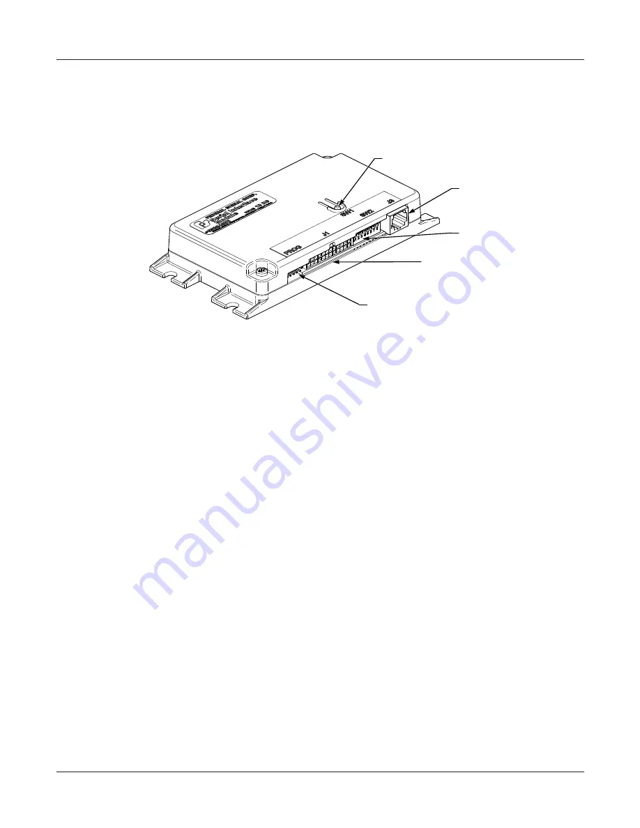
Figure 2 Connectors and switches on the Serial Interface Module
J3 CONNECTOR FOR
SERIAL CABLE FROM
LIGHT BAR
J1 CONNECTOR FOR 24-CONDUCTOR
CABLE SUPPLIED WITH SERIAL
INTERFACE MODULE
SW2 DIP SWITCHES (SEE
TABLE 3.1 ON PAGE 13)
PROGRAMMING HEADER FOR CLONING
FLASH PATTERNS FROM VEHICLE TO
VEHICLE. (SEE THE INSTRUCTIONS
INCLUDED WITH THE PROGRAMMER.)
SW1 PUSHBUTTON FOR
SELECTING FLASH PATTERNS
290A7702
Selecting a Flash Pattern for Modes 3, 2, 1, and Intersection
The three modes operate with Mode 3 having the highest priority: Mode 3 overrides
Mode 2, and Mode 2 overrides Mode 1. When the light bar operates in one of these
modes, the SignalMaster modules keep sequence with the flash pattern.
You can change default Mode flash patterns by programming each mode with one of
patterns in the light bar’s library. A typical setup would be:
• Mode 1:
Rear LEDs
• Mode 2:
Front/Rear LEDs
• Mode 3
: Siren (SmartSiren
®
or Federal Signal compatible), Front/Rear LEDs, and
Flash Takedown/Alley LEDs on the main bar
• Modes 1 and 2:
Front/Rear Cutoff
NOTE:
If the light bar needs to be programmed after you connect a progressive slide
switch, the programming sequence must be Mode 3, Mode 2, Mode 1, Intersection.
When you press and release the SW-1 pushbutton on the Serial Interface Module
to select a pattern, the light bar briefly turns off and then displays the next pattern.
To cycle backwards to a previous pattern, move Switch 5 to ON (up position) on
SW2.
Mode 3
1.
Apply 12 Vdc (+BAT) to the Mode 3 control wire (black/red) from the Serial
Interface Module to display the assigned pattern.
2.
On the Serial Interface Module, press and release the SW-1 pushbutton until the
pattern you want appears on the light bar.


