background image

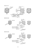
-18- 


ESM-90-H-120


ESM-104-H-200


ESM-104-H-400


Содержание Ezi-SPEED ESD-30-C

Страница 1: ......

Страница 2: ...haracteristics of motor torque 19 5 Specifications and dimensions of the gearhead 21 5 1 Specifications 21 5 2 Dimensions 22 6 Installing and wiring 27 6 1 Cautions on installations 27 6 2 External wi...

Страница 3: ...load and permissible thrust load 43 7 Setting and Operation 44 7 1 Exterior and names 44 7 2 Rotation direction switch 45 7 3 Connecting 46 7 3 1 Connection the power supply 46 7 3 2 Connecting the mo...

Страница 4: ...etting range of the rotation speed 78 9 System diagram 80 9 1 System diagram 80 10 Troubleshooting and remedial actions 81 10 1 Alarm 81 10 2 Warning 84 10 3 Troubleshooting and remedial actions 84 10...

Страница 5: ...contact with FASTECH s agents or our company at the address on the last page of the manual Our company is not responsible for a product breakdown due to user s dismantling for the product and such a b...

Страница 6: ...user s foot may get injured by dropping the product Use non flammable materials such as metal in the place where the Ezi SPEED is to be installed Otherwise a fire may occur When installing several Ez...

Страница 7: ...und of the internal circuit by the condenser Please Ground the Ezi SPEED Otherwise an electric shock or a fire may occur and a cause of malfunction of machine Operating and setting change Attention If...

Страница 8: ...is Ezi SPEED Electricity remaining in the condenser may cause of electric shock Do check and repair after a minute Do not change cabling while power is being supplied Otherwise the user may get injure...

Страница 9: ...9 2 Characteristics 2 1 Part number...

Страница 10: ...i SPEED 60 H 30 C R15 P ESG 60 H R15 P 1 15 Ezi SPEED 60 H 30 C R15 H ESG 60 H R15 H Ezi SPEED 60 H 30 C R20 P ESG 60 H R20 P 1 20 Ezi SPEED 60 H 30 C R20 H ESG 60 H R20 H Ezi SPEED 60 H 30 C R30 P ES...

Страница 11: ...90 H 120 C R20 P ESG 90 H R20 P 1 20 Ezi SPEED 90 H 120 C R20 H ESG 90 H R20 H Ezi SPEED 90 H 120 C R30 P ESG 90 H R30 P 1 30 Ezi SPEED 90 H 120 C R30 H ESG 90 H R30 H Ezi SPEED 90 H 120 C R50 P ESG 9...

Страница 12: ...items to sales office from which you purchased the parts Standard Motor and Drive Combinations Motor 1 EA Drive 1 EA Connection cable 1 EA Only models with a supplied connection cable CN1 connector 5...

Страница 13: ...Phase 0 51A Single Phase 1 55A Three Phase 0 90A Single Phase 2 43A Three Phase 1 41A Single Phase 3 42A Three Phase 1 97A Single Phase 5 64A Three Phase 3 26A Maximum input Current Single Phase 1 9A...

Страница 14: ...0 C Non freezing Humidity 35 85 Non condensing Elevation Elevation of 3000m 10000ft or less Environment No corrosive gas and dust No splashing water and oil No used at special environment like a radio...

Страница 15: ...15 3 2 Dimensions 30W 60W 120W Drive 200W 400W Drive...

Страница 16: ...70 120 160 160 170 20mm from Shaft N 100 140 170 160 170 Promissible Thrust Load N Please don t thrust load An unavoidable situation please keep thrust load less than 50 of motor weight General speci...

Страница 17: ...17 Operation Environment Temperature 0 40 Humidity 85 or less Environment No corrosive gas and dust Storage Environment Temperature 20 70 Humidity 85 or less 4 2 Dimensions ESM 60 H 30 ESM 80 H 60...

Страница 18: ...18 ESM 90 H 120 ESM 104 H 200 ESM 104 H 400...

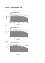
Страница 19: ...19 4 3 Characteristics of motor torque 30W 60W 120W...

Страница 20: ...20 200W 400W...

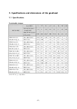
Страница 21: ...P 100 3000 r min 1 8 3 6 5 4 7 2 10 3 17 2 30 30 4000 r min 1 4 2 7 4 1 5 4 7 7 12 9 25 8 27 ESM 104 H 200 ESG 104 H R P 100 3000 r min 2 9 5 9 8 8 11 7 16 8 28 52 7 70 4000 r min 2 4 1 6 1 8 1 11 6...

Страница 22: ...H 200 ESG 104 H R P 4 2Kg ESM 104 H 400 ESG 104 H R P ESM 60 H 30 ESG 60 H R H 1 2Kg ESM 80 H 60 ESG 80 H R H 2 2Kg ESM 90 H 120 ESG 90 H R H 3 3Kg 5 2 Dimensions ESM 60 H 30 ESG 60 H R P Motor Part N...

Страница 23: ...Mounting Bolt ESM 80 H 60 ESG 80 H R P 5 20 41 M6 P 1 0 65 30 100 46 M6 P 1 0 70 200 51 M6 P 1 0 75 ESM 90 H 120 ESG 90 H R P Motor Part Number Gearhead Part Number Gear Ratio L Length mm Mounting Bol...

Страница 24: ...0 ESG 104 H R P Motor Part Number Gearhead Part Number Gear Ratio L Length mm Mounting Bolt ESM 104 H 200 ESG 104 H R P 5 20 60 M8 P 1 25 95 30 50 72 M8 P 1 25 110 100 200 86 M8 P 1 25 120 ESM 104 H 4...

Страница 25: ...L Length mm Mounting Bolt ESM 104 H 400 ESG 104 H R P 5 20 60 M8 P 1 25 95 30 50 72 M8 P 1 25 110 100 200 86 M8 P 1 25 120 ESM 60 H 30 ESG 60 H R H Motor Part Number Gearhead Part Number Gear Ratio Mo...

Страница 26: ...Part Number Gearhead Part Number Gear Ratio Mounting Bolt ESM 80 H 60 ESG 80 H R H 5 200 M6 P 1 0 70 ESM 90 H 120 ESG 90 H R H Motor Part Number Gearhead Part Number Gear Ratio Mounting Bolt ESM 90 H...

Страница 27: ...at area free of dust iron powder and salt 6 Install at area not subject to continuous vibration or excessive shocks 7 Install at area free electronic noise from welder power machine etc 8 When instal...

Страница 28: ...o not install any device that generate a large heat or noise near drive If ambient temperature of the drive exceeds 40 please change ventilation condition or forced cool with cooling fan 6 2 External...

Страница 29: ...doing the assembly special care should be taken neither to exert excessive force on the motor shaft nor to hit inside of the gearhead Otherwise the gear will get damaged resulting in an abnormal noise...

Страница 30: ...ion Do not forcibly assemble the motor and gearhead Also do not let metal objects or other foreign matter enter the gearhead The motor shaft or gear may be damaged This will be reason of noise or shor...

Страница 31: ...sion efficiency The rotation direction of gearhead shaft is decided same rotation direction with motor and oppsite rotation direct with motor on the gear ratio When using decimal gearhead ratio 1 10 t...

Страница 32: ...rs per day 4 Bearing temperature 80 Ball bearing type Service factor of above conditions is SF 1 If using ball bearing type gear head by 24 hours service factor will be 1 5 so life time will be reduce...

Страница 33: ...f the calculated overhung load value is used in excess of the permissible limit below data sheet the bearing will be damaged within a short period of time causing the output shaft to warp and cause fa...

Страница 34: ...ESM 104 H 200 ESG 104 H R P 5 300 400 10 20 400 500 30 200 500 650 ESM 104 H 400 ESG 104 H R P 5 300 400 10 20 400 500 30 200 500 650 6 4 Installing the combination hollow shaft gearhead 6 4 1 Checkin...

Страница 35: ...an headed screw 6 6 25 1R 6 4 2 Cautions on operations Checking the part number of motor gearhead Checking the part number of motor and gearhead that can be assembled When installing gearhead do not d...

Страница 36: ...direction of the gearhead shaft Cable will hit the casing of gearhead so do not wiring Do not add additional adhesive to the pilot sections of the motor and gearhead Also assemble the motor and gearh...

Страница 37: ...fix with the supplied hexagonal socket head bolt set to the metal machining flat plate When installing gearhead please make mounting holes in the metal machining flat plate Install the supplied hexag...

Страница 38: ...able apply when the supplied hexagonal socket head bolt in used Part number Maximum applicable plate thickness mm ESG 60 H R H 5 ESG 80 H R H 8 ESG 90 H R H 12 of part number indicates a number of gea...

Страница 39: ...Unit of mounting holes dimension is mm Mount the load shaft When mounting the load shaft on the hollow shaft align the centerline of the hollow shaft with the centerline of the load shaft The hollow...

Страница 40: ...40 Stepped load shaft Fixing method using the end plate Use the flat washer and spring washer on the end plate Tighten with hexagonal socket head bolt...

Страница 41: ...stop ring Tighten with hexagonal socket head bolt Part number Diameter of Hollow shaft H8 Tolerance of load shaft h7 ESG 60 H R H 12 0 0 027 12 0 018 0 ESG 80 H R H 15 0 0 027 15 0 018 0 ESG 90 H R H...

Страница 42: ...ction of gearhead When viewed from the front view and the rear view the rotation direction of hollow shaft is different Transmission efficiency of gearhead Part number 5 10 15 20 30 50 100 200 ESG 60...

Страница 43: ...ed both the permissible overhung load and the permissible thrust load simultaneously with below chart Permissible overhung load and permissible thrust load Part number Gear Ratio Permissible Overhung...

Страница 44: ...etting and Operation 7 1 Exterior and names Drive 30W 60W 120W 200 400W Motor cable Gearhead Mounting holes 4 locations Output shaft 4Pin motor connector 6Pin sensor connector Protective Earth Termina...

Страница 45: ...r CN3 Connects to the signal connector of the motor Motor Connector CN2 Connects to the power connector of the motor I O Signal Connector CN4 Connects with the I O signals Main Power Connector CN1 Con...

Страница 46: ...n direct with motor on the gear ratio Part Number Gear Ratio Same rotation direction with motor Oppsite rotation direct with motor ESG 60 H R P 5 10 15 20 200 30 50 100 ESG 80 H R P ESG 90 H R P ESG 1...

Страница 47: ...ect the R S and T phase lines to the L1 L2 and L3 terminals each Single Phase 200 240V Three Phase 200 240V Connecting of lead wire Lead wire Size AWG18 14 0 75 2 0 2 Length of lead wire stripping 8mm...

Страница 48: ...d the sensor connector 6pins to CN3 Use optional relay cable when extending between motor and drive Up to two cables can be connected The distance between the motor and drive can be extended up to 10m...

Страница 49: ...ion of motor Ground terminal Use crimp style terminal Ring crimp style terminal with insulation Teminal screw size M4 Motor ground connection 200W 400W motor can ground directly on the motor 7 3 4 Con...

Страница 50: ...e polarity For every rotation of the motor 30 pulses are output 9 Y0 10 Y1 Output AL on Free polarity Free polarity Free polarity It turns off when an alarm is generated N ormally closed 11 Y1 12 Y2 O...

Страница 51: ...or SPEED OUT output allow a 5mA current or more to flow In the case of using a external controller with a built in clamp diode If an external controller with a built in clamp diode is used a leakage p...

Страница 52: ...52 Connection example for I O signals and programmable controller This is connection example for operating a motor using a transistor output type programmable controller...

Страница 53: ...DC20 4V 28 8V 100mA or more Turn on the external power before turning on the main power of the drive For the Y0 Y1 and Y2 be sure to keep the current value at 100mA or less If the current exceeds thi...

Страница 54: ...input power Single phase 200 240 Three phase 200 240V Regenerative resistor Sensor connector 6Pins Connect to CN3 Motor connector 4Pins Connect to CN2 Main power connect to CN1 Protective earth termin...

Страница 55: ...not operated motor Set the operation switch from RUN to STAND BY for release an alarm before use motor Pervention of operation at power on alarm is refered to manual 10 1 Alarm 7 4 3 Operating After...

Страница 56: ...the motor to start rotating at the set rotation speed Changing the rotation direction Change the rotation direction of the motor gearhead using the rotation direction switch The rotation direction ca...

Страница 57: ...ternally The factory setting is OFF When The External operation signal input parameter is ON External I O control is enabled but the front control of the drive is disabled When The External operation...

Страница 58: ...d Timing chart example In case of parameter external operation signal input to on and the rotation direction switch is set to FWD Operation input The motor rotates when either FWD input or REV input i...

Страница 59: ...59 Data setting method Example Set the rotation speed to 3000rpm Change from 0 rpm Refer to manual 8 2 Setting and 7 segment display about change of 7 segment...

Страница 60: ...mber suing the P0 P1 and P2 inputs 3 When the FWD or REV input is turned ON the motor will rotate 4 Switch the operation data number using the P0 P1 and P2 inputs 5 When the FWD or REV input switch ha...

Страница 61: ...creasing Display converting the motor rotation speed into the increasing speed 8 4 Actual rotation speed Display the actual rotation speed of the motor output shaft 8 4 Load factor Display the load to...

Страница 62: ...speed 8 9 Operating using I O signals inputs Operates by inputting signals externally 7 3 4 7 5 Disables an operation with the setting button on the front panel 8 4 Operates with multiple speeds up t...

Страница 63: ...63 8 2 Setting and 7 segments display 1 Monitor mode...

Страница 64: ...64 2 Input Output setting mode...

Страница 65: ...65 3 Parameter setting mode 1page...

Страница 66: ...66 3 Parameter setting mode 2page...

Страница 67: ...67 3 Parameter setting mode 3page...

Страница 68: ...68 3 Parameter setting mode 4page...

Страница 69: ...69 4 NVM saving mode...

Страница 70: ...the speed reduction ratio relative to the rotation speed of the motor output shaft Displays the speed calculated based on the speed reduction ratio on the monitor mode If the speed reduction ratio fo...

Страница 71: ...2 P0 X3 input function selection in 3 P1 X4 input function selection in 4 A rSt External output function oUt External output setting Y0 output function selection oUt 0 Assigns the output signals to th...

Страница 72: ...and REV input is set to ON at the same time rEv REV P0 Operation data 0 These signals are used to select the operation data number 8 speeds c an be specified by using three opertation datas P1 Operati...

Страница 73: ...rotation speed Actual rotation speed rpm 0 Monitors the rotation speed of gearhead Monitors the rotation speed of the gear output shaft or conveyor speed when the speed reduction ratio parameter is se...

Страница 74: ...is unlit Input signal Output signal Display of the rotation speed Displayed digit number when setting the speed reduction ratio or speed increasing ratio Since the number of significants figures for t...

Страница 75: ...t shaft rotation speed When the calculated conveyor speed reduction ratio is used the conveyor speed is converted as follows Example the pully diameter is 0 2m and gear ratio of the gearhead is 50 50...

Страница 76: ...y setting Operation data number 0 7 Rotation speed sPd0 sPd7 50 4000 r min 100 Acceleration time tA0 tA7 0 0 15 0 sec 0 5 Deceleration time td0 td7 Torque limit tq0 tq7 10 300 300 Initialize Ini0 ini7...

Страница 77: ...e can be set in the parameter in normal operation without operation data Setting to the operation data If you want to set the acceleration time and deceleration time of each data in data mode you can...

Страница 78: ...que limit can be set via parameters Factory setting is 300 and can be set from 10 to 300 8 8 Lock of setting data Press and hold the S button can be lock of setting data If the setting data is locked...

Страница 79: ...already set in the operation data the rotation data set in the speed upper limit will be overwritten Speed lower limit Set the lower limit value of the rotation speed in the speed lower limit of the s...

Страница 80: ...9 1 System diagram 30W 60W 120W motor 30W 60W and 120W motors have one line with motor relay cable and sensor relay cable 200W 400W motor 200W and 400W motors have two lines with motor relay cable an...

Страница 81: ...tantaneously at the time of external stop At Et After the motor is stopped the motor shaft is free status Alarm list Alarm code Alarm type Cause Remedial action Alarm reset AL Alarm recode delete AL U...

Страница 82: ...AL OL Overload 1 A load exceeding the continuous duty region was applied to the motor for the time exceeded the value set in the The overload alarm detection time parameter 2 The motor was started ru...

Страница 83: ...rate properly after the power is cycled the internal circuit may be damaged Contact your nearest sale office Continuing the operation without removing the cause of the alarm may cause malfunction of t...

Страница 84: ...r turn on Warning records Up to 10 generated warnings are saved in the RAM in order of the latest to oldest When clearing the warning records perform the warning record clear on the monitor mode Atten...

Страница 85: ...eing OFF Both the FWD input and REV input are being ON Turn either of the FWD input or REV input ON An alarm is present A protective function is triggered and an alarm generates Refer to 10 1 Alarm an...

Страница 86: ...sed The speed lower limit has been set Lower the value of speed lower limit parameter Maximum speed lower value is 50rpm Motor operation is unstable The motor gearhead output shaft is not misaligned w...

Страница 87: ...screws loose Tighten the screws 2 Are there any abnormal noises in the motor ball bearing or other parts Stop using the product immediately contact to the technical support center 3 Are there any abn...

Страница 88: ...D S 005F 7 CSPD A 007F CSPD M 007F CSPD S 007F 10 CSPD A 010F CSPD M 010F CSPD S 010F Wiring Diagram Connector of drive side Connection Connector of motor side Pin plan Pin number Pin plan Pin number...

Страница 89: ...on Pin plan 1 YELLOW 5V_E Purpose ITEM Specification Manufacturer Motor side Housing 5557 06R MOLEX Motor side Terminal 5556T MOLEX 2 BLOCK Shield 3 GREEN GND_E 4 BROWN HALL_U 5 WHITE HALL_V 6 ORANGE...

Страница 90: ...control system equipment used with the other control system equipment configuration of electrical parts wiring layout hazard level and the like You must be verified through conducting EMC measures on...

Страница 91: ...ll the AC Line Filter as close to drive as possible Use cable clamps and other means to secure the input and output cables firmly to the surface of the enclosure Connect the ground terminal of the AC...

Страница 92: ...the drive to malfunction or suffer damaged Be sure to ground the product to prevent it from being damaged by static electricity Expect when operating the setting button or switch on the drive front p...

Страница 93: ...or loss please contact Head Quarter of Fastech or our distributors The user manual can be changed without pre notification in order to reflect improvement or change of the product specifications and f...

Отзывы: