


-51-
•
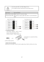
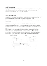
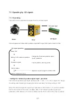
Logic of input signal
Input signal is photocoupler input. It operate with internal power (+15V) or external power. When
use external power, can use sink logic input and source logic input with change wiring.
Use external power : DC24 V
−
15% ~ +20%, 100 mA or more
•
Logic of output signal
Output signal is photocoupler and open collector output. ON voltage of output circuit is max 1.5V.
When operate each element with output signal circuit, consider the ON power.
External power : DC4.5 ~ 30 V, 100 mA or less. (For SPEED-OUT output, allow a 5mA current or
more to flow.)
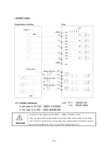
•
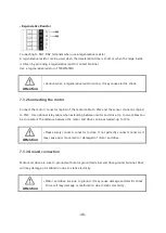
In the case of using a external controller with a built-in clamp diode
If an external controller with a built-in clamp diode is used, a leakage path may form and cause
the motor to operate even when the external controller power is off, as long as the drive power is
on.
Since the power capacity of the controller is different from that of the drive, the motor may
operate when the external controller and drive powers ate turned on or off simultaneously.
When powering down, turn off the drive power first, followed by the external controller power.
When powering up, turn off the external controller power first, followed by the drive power.
Содержание Ezi-SPEED ESD-30-C
Страница 1: ......
Страница 9: ...9 2 Characteristics 2 1 Part number...
Страница 15: ...15 3 2 Dimensions 30W 60W 120W Drive 200W 400W Drive...
Страница 18: ...18 ESM 90 H 120 ESM 104 H 200 ESM 104 H 400...
Страница 19: ...19 4 3 Characteristics of motor torque 30W 60W 120W...
Страница 20: ...20 200W 400W...
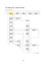
Страница 63: ...63 8 2 Setting and 7 segments display 1 Monitor mode...
Страница 64: ...64 2 Input Output setting mode...
Страница 65: ...65 3 Parameter setting mode 1page...
Страница 66: ...66 3 Parameter setting mode 2page...
Страница 67: ...67 3 Parameter setting mode 3page...
Страница 68: ...68 3 Parameter setting mode 4page...
Страница 69: ...69 4 NVM saving mode...