background image

35

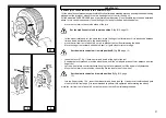
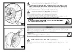
below:

 P

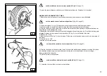
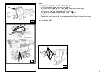
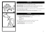
ADJUSTMENT OF THE TOOL HOLDER CARRIAGE SLIDES

a)  Disconnect the machine from electrical network

b)  Loosen the screws 

(3 fig. J/4)

 related to each upper slide of the carriage 

c)  Loosen the 4 register locking nuts 

(4 fig. J/4)

d)  Turn each of the slide adjusting screws by 1/4 of turn.

e)  Tighten the screws for locking the upper slides 

(3 Fig. J/4)

f)  Tighten the register locking nuts 

Repeat the a.m. operation for the chuck carriage as in fig. J5 and the tool holder carriage.

Note:

 in case adjusting is insufficient to eliminate the play, repeat the a.m. operations once again until the 

play is eliminated in full.

J/3

J/5

2

1

31

J/4

4 3

4

3

Содержание RGU588E

Страница 1: ...UNIVERSAL TYRE CHANGER INSTALLATION USE AND MAINTENANCE GUIDE RGU588E ed 09 15 Cod 3014834 V Original instructions ...

Страница 2: ... POSITION page 15 12 CHECK OF CORRECT OPERATION page 15 13 USE page 17 13 1 Wheel clamping page 17 Clamping of alloy rims page 18 Clamping extensions page 19 13 2 Tubeless and supersingle wheels page 19 Bead breaking page 19 Removing page 21 Mounting page 22 13 3 Tube tyres page 25 Bead breaking page 25 Removing page 26 Mounting page 26 13 4 Wheels with split ring page 29 Bead breaking and removin...

Страница 3: ...R IN NEED GENERAL SAFETY REGULATIONS 3 The use of this machine is strictly reserved to trained and authorized staff Any tampering or modification if not previously authorized by manufacturer relieves this one of all possible damages referred to the mentioned actions Any removal or tamper with the safety devices installed in this machine will represent a violation of the European regulations Anywor...

Страница 4: ...g it from burning out If the tyre changer is equipped with the RC Radio Control the mobile control stand is connected with the machine frame through a steel wire that prevents the operator from going too far so working without seeing the machine CAUTION Removing or tampering with safety devices represents a violation of the European Safety Regulations and relieves the manufacturer of any and all l...

Страница 5: ...3m high ATTENTION The dimensions above also refer to the working area Bystanders and persons other than trained and authorized staff are strictly forbidden to enter this area Set the forks of the lift truck into the slots 1 and 2 made in the machine baseframe expressly to move it and set it in position It is furthermore possible to use the hooks placed at the machine corners and those on the chuck...

Страница 6: ...freely move and follow the stroke the chuck holder without risk of damage Failure to comply with above mentioned requirements will relief the manufacturer from any and all liability for any injury to persons or damage to things referred to these acts and it will involve the immediate expiry of warranty Check the tyre changer to the network turn on the main switch 5 fig A and check the rotation dir...

Страница 7: ...in position I right it controls opposite rotation so bringing the tools in the initial condition Switch 3 3 fig C if pushed up to position L it makes the chuck rotate at the double of the speed set when selecting position M up Switch 4 4 fig C let the chuck holder arm and the tool holder arm move at the same time either at high speed pos N or at reduced speed pos O Switch 5 5 fig C if pushed up to...

Страница 8: ...ck arm 9 Chuck 10 Jaws 11 Main switch 12 Base platform 13 Tool holder carriage 14 Tool holder 15 Chuck carriage 16 Chuck holder carriage 17 Bead breaking disk 18 Finger tool 19 Tool fastening knob ATTENTION Keep as far as possible from moving parts Necklaces bracelets and too large clothes can be a source of danger for the operator For the same reason long hair must be tied up D A 12 11 18 19 17 1...

Страница 9: ...12 3008615 3006037 3014771 3014772 3005417 3014774 3014775 3000961 3008614 3008616 3014337 3005087 3005410 3005423 3005419 3014767 3006037 3006038 3005421 ...

Страница 10: ...r missing stickers must be immediately replaced Do not use the tyre changer if one or more stickers are missing Do not add any object that could prevent the operator from seeing them 3014776 3000964 3014770 3000965 3014773 3000961 3014768 3014769 ...

Страница 11: ... utmost attention during tool holder tilting operation Danger of crushing feet during chuck rotation or opening operation Danger of crushing between chuck holder and tyre changer platform Danger of crushing between chuck and tool Danger of wheel falling down Live electric voltage ...

Страница 12: ...r 14 Fig D must tilt to rest position CHECK OF CORRECT OPERATION 12 Move the joystick 2 Fig C page 9 DOWN pos G the tool holder 14 Fig D must tilt and hook into work position Move the joystick leftwards pos H tools must rotate by 180 on their axle counterclockwise move the joystick rightwards pos I tools must reverse rotation and go back to initial position 2 With tool holder in rest position move...

Страница 13: ... operations above moving the switch lever ref 3 fig C page 9 movements must take place at different speed ATTENTION When the chuck holder moves down it creates potential crushing points Always work in the positions given by this guide keeping outside the action range of moving arms ATTENTION During the chuck jaws opening closing movement there s the risk of potential crushing points Always work in...

Страница 14: ...AMPING USE 13 WARNING In clamping phase make sure the clamps have been correctly positioned on the rim so preventing the wheel from falling off WARNING This operation can be extremely dangerous Do it manually only if you are certain you can keep the wheel balanced Heavy tyres over 110kg and or oversize tyres with diameter over 130cm shall never be lifted by hand Let them roll on floor and lift the...

Страница 15: ...90 alloy rim gripper CLAMPINGOF ALLOY RIMS 4 Use the joystick to keep on moving the chuck arm up and down to centre the chuck 9 fig A to the rim 5 With the jaws 10 fig A closed move the chuck against the wheel then use the switch 5 fig C page 9 to open the jaws so clamping the rim from inside in the most suitable position according to the kind of rim to be chosen among those shown in Fig E1 E2 E3 ...

Страница 16: ...NTION The bead breaking disk must not be pressed against the rim but against the tyre bead 4 Use the joystick to position the wheel in a way to let the rim outer profile graze the bead breaking disk fig F Rims having diameter over 46 without central hole flange can be clamped with the kit of 4 extensions item 140 90 available on demand Insert the extension on the support bayonet like mounting and ...

Страница 17: ...profile as well as possible 6 Go on until the first bead is fully detached To facilitate this operation grease tyre bead and rim edge while the wheel is rotating ATTENTION To avoid any risk when greasing the beads make the wheel rotate CLOCKWISE if you are greasing the outer bead COUNTERCLOCKWISE if you are greasing the inner bead 8 Use the joystick 1 fig C page 9 to move chuck and tool arm until ...

Страница 18: ...present any particular difficulty after bead breaking proceed pushing the bead breaking disk against the tyre inner side until the two beads get out of the rim see fig H 2 if the wheel is a SUPERSINGLE type or particularly hard anyway it is not possible to proceed as described above In this case it is necessary to use the finger tool and proceed as described below move the tool arm to the outside ...

Страница 19: ...the disk or the finger tool If the wheel doesn t present any particular difficulty it is suggested to use the disk otherwise the finger tool will be required MOUNTING OPERATION WITH DISK Proceed as follows 1 if the rim is released by the self centering chuck clamp it again as described in par WHEEL CLAMPING 2 grease beads and rim 3 set the in the highest position of rim outer edge see fig M 4 Set ...

Страница 20: ... on the machine baseframe Set the mobile control unit in work position C fig B 8 13 close the chuck jaws completely taking care to hold the wheel to prevent it from falling off ATTENTION This operation can be extremely dangerous Do it manually only if you are certain you can keep the wheel balanced Heavy tyres over 110kg and or oversize tyres with diameter over 130cm shall never be lifted by hand ...

Страница 21: ...e inserted in position 6 remove the gripper 7 Let the tool out of the tyre 8 move the tool arm to rest position then move it to the tyre outer side and hook it in this position 9 let the tool rotate by 180 10 mount the gripper in the lowest position at 6 o clock out of the second bead see fig N Set the mobile control unit in work position C fig B 8 page 21 Set the mobile control unit in work posit...

Страница 22: ...bead gets hooked by the tool 3 Move the rim 4 5 cm from tool in order to prevent the bead from releasing 4 Move the finger tool outwards until its red spot is in proximity of the rim outer edge TYRE REMOVING Set the mobile control unit in work position C fig B 8 page 21 5 Insert the lever see fig P between rim and bead at the right of the tool 6 Keep the lever pressed down while lowering the wheel...

Страница 23: ... the tool right side see fig Q 14 keep the lever pressed and lower the wheel until the rim edge is at about 5 mm distance from the finger tool then turn the wheel counterclockwise until the tyre is fully pulled out ATTENTION The detachment of the beads might cause the tyre to fall down Always make sure there are no by standers inside the working area TYRE MOUNTING 1 If the rim has been removed fro...

Страница 24: ...move the gripper Set the mobile control unit in work position C fig B 8 page 21 10 Pull the tool out of the tyre 11 Set the tool arm in rest position and move it to the outer side of the tyre 12 Turn the tool by 180 Set the mobile control unit in work position C fig B 8 page 21 13 Turn the chuck until the valve is set in the lowest position at 6 o clock 14 Lower the chuck until the tyre rests on t...

Страница 25: ... finger tool proper seat 24 Keep the lever pulled so guiding the bead into the rim groove and keep rotating until the tyre is fully mounted 25 Remove the gripper Turn the chuck counterclockwise while moving the tool outwards to pull it out 26 Tilt the tool arm to rest position 27 Lower the chuck until the wheel rests on the platform 28 Make sure that the valve is perfectly centred to the outlet ho...

Страница 26: ...lever 23 fig Z page 28 or with the help of the disk 7 Remove the split ring 8 Move the tool arm 14 fig W from rim edge Release the ratchet tilt the arm to rest position and move it to the inner side of the wheel 9 Turn the tool by 180 Lower the arm to work position 10 Turn the chuck and at the same time move the disk forward with short steps following the rim profile until the second bead is fully...

Страница 27: ... position set the mobile control unit in work position B fig B 8 page 21 11 Lower the chuck until the tyre rests on the platform 2 Lower the tool arm 14 fig D to work position until it gets hooked with the proper ratchet 3 Use the joystick to position the wheel in a way that the disk grazes the rim outer edge 4 Turn the chuck and at the same time move the disk forward until the split ring is fully...

Страница 28: ...disk is level with tyre bead 19 Turn the chuck and at the same time move the disk forward until the tyre is fully pulled out of the split ring Note it is possible to avoid this double bead breaking operation with the use of item 136 90 KIT OFGRIPPERS optional that enables to fix split ring and rim together so detaching them at the same time ATTENTION The detachment of the tyre from rim causes the ...

Страница 29: ...the chuck until positioning is completed 7 Set the split ring on rim and then mount the lock ring with the help of the disk as shown in Fig Y 8 Move the tool arm to rest position and close the chuck jaws completely taking care to hold the wheel to prevent it from falling off set the mobile control unit in work position B fig B 8 page 21 ATTENTION This operation can be extremely dangerous Do it man...

Страница 30: ...il the O ring seat gets uncovered 8 grease the O ring and set it into its seat 9 Set the lock ring on rim with the help of the disk as shown in Fig Y Move the tool arm to rest position and close the chuck jaws completely taking care to hold the wheel to prevent it from falling off ATTENTION This operation can be extremely dangerous Do it manually only if you are certain you can keep the wheel bala...

Страница 31: ...Equivis ZS Castrol Hyspin AWH HV BP Bactram HV Chevron Ep Hydraulic Oil HV Remove the cap 30 fig J 2 fill the tank with new oil and screw the cap back on 3 periodically check oil level in the gear unit that with chuck arm fully lowered at the end of its stroke shall never uncover completely the sight glass placed on the gear casing If necessary top up with oil ESSO SPARTAN EP320 or alike AGIP F1 R...

Страница 32: ...s 4 fig J 4 d Turn each of the slide adjusting screws by 1 4 of turn e Tighten the screws for locking the upper slides 3 Fig J 4 f Tighten the register locking nuts Repeat the a m operation for the chuck carriage as in fig J5 and the tool holder carriage Note in case adjusting is insufficient to eliminate the play repeat the a m operations once again until the play is eliminated in full J 3 J 5 2 ...

Страница 33: ...draulic power pack doesn t work CAUSE 1 the magneto thermal switch is engaged 1 call for technical aid to find out the problem and restore the machine functioning ATTENTION Dispose of the used oil according to the national laws in force ATTENTION if in spite of the above mentionedindications thetyre changer does not work properly DO NOT USE it and call for technical assistance There s a slowing do...

Страница 34: ... the tool arm carriage By means of adequate lifting bands as well as a fork lift truck move the tyre changer as shown in fig A Keep the hooks for any further need of moving the machine to a new installation site In case of storage for a long period 3 4 months or longer it is necessary 1 To close the chuck jaws lower the chuck arm set the tool arm in work position lowered 2 To disconnect the machin...

Страница 35: ...APPING Whenever you decide to scrap the machine it is advisable to make it unusable by disconnecting it from power supply Being the machine considered as a special waste demount it in homogeneous parts and dispose of them according to the national regulations in force Dispose of the package materials through the relevant collection centres 1 2 8 9 3 7 5 6 4 Attention For a correct waste disposal c...

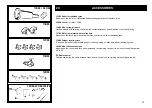
Страница 36: ...n the chuck jaws they allow working on alloy rims without damaging them 138 90 Gripper for alloy rims To be used instead of the standard gripper It allows working on alloy rims without damaging them 140 90 Kit of chuck extensions Mounted on the chuck jaws they allow extending the clamping range of rims without central flange from 48 to 56 RC Radio control It allows eliminating the cable between ma...

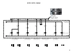
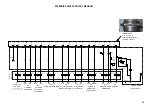
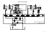
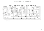
Страница 37: ...40 ELECTRIC AND HYDRAULIC DIAGRAMS ...

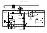
Страница 38: ... XL1 3 MOTORE ROTAZIONE MANDRINO 400V 4 5 7A 230V 6 5 9 5A 1 5 2 2 KW 1500 3000 RPM M1 XL1 4 1 2 3 4 5 6 KM2 1 2 3 4 5 6 KM5 XL1 5 INTERRUTTORE AUTOMATICO Imax 10A 230V Q2 XL1 6 XL1 7 SPINA 32A 3P N T SPINA INTERRUTTORE GENERALE Q1 MOTORE POMPA DELL OLIO 400V 7 2A 230V 13A 3KW 1400RPM M2 1 2 3 4 5 6 KM6 INTERRUTTORE AUTOMATICO Imax 13 5A 230V Q3 XL1 8 XL1 9 XL1 10 XL1 11 1A AM F3 1A AM F2 0 230 20...

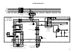
Страница 39: ... 1 2 3 4 5 6 KM3 02 2 1 2 3 4 5 6 KM4 02 6 1 2 3 4 5 6 KM1 02 8 XL1 L14 XL1 L15 XL1 L16 MOTORE ROTAZIONE MANDRINO 400V 4 5 7A 230V 6 5 9 5A 1 5 2 2 KW 1500 3000 RPM Cod 4595863 M1 XL1 PE 1 2 3 4 5 6 KM2 02 10 1 2 3 4 5 6 KM5 02 4 XL1 L17 INTERRUTTORE AUTOMATICO Imax 6 3A 400V Q2 XL1 L18 XL1 L19 SPINA 32A 3P N T SPINA INTERRUTTORE GENERALE Q1 MOTORE POMPA DELL OLIO 400V 7 2A 230V 13A 3KW 1400RPM Co...

Страница 40: ... 61 4 51 51 51 51 51 51 51 51 51 51 51 51 48 3 12 11 1 61 61 61 61 61 18 49 13 28 2 14 27 26 17 5 5 5 5 15 01 4 0 1 S15 02 6 02 5 S1 V2 S4 V3 S15 02 2 V28 S2 V4 S15 02 2 V29 S3 V5 S14 V6 S13 V7 S17 V8 S18 V9 S11 S12 S27 V14 S26 V15 V16 SELEZ VELOCITA DI ROTAZIONE MANDRINO SELEZIONE SENSO DI ROTAZIONE MANDRINO ORARIO ANTIORARIO PEDALE BASCULANTE INTERRUTTORE 2 POS STABILI 6 5 n RIFERIMANTO AL LAYOU...

Страница 41: ... MANDRINO ATTIVAZIONE MOTORE POMPA CPC 9 CPC 22 CPC 23 CPC 7 CPC 10 CPC 24 CPC 8 46 9 9 9 9 7 45 44 43 22 23 42 8 47 25 25 25 25 41 01 15 01 15 24Vac 400V 12A A1 A2 KM3 21 22 KM4 02 6 24Vac 400V 12A A1 A2 KM5 21 22 KM3 02 2 24Vac 400V 12A A1 A2 KM4 21 22 KM5 02 4 24Vac 400V 12A A1 A2 KM1 21 22 KM2 02 10 21 22 KM1 02 8 24Vac 400V 12A A1 A2 KM2 24Vac 400V 16A A1 A2 KM6 15 16 KT1 02 14 TIMER DISATTIV...

Страница 42: ...12 Y26 Y13 Y18 Y3 SU GIU SX DX GIU SU SX DX APRI CHIUDI SU GIU IN TP TP Y15 ON BASSA VEL Y15 OFF ALTA VEL CPC 6 CPC 15 CPC 1 CPC 4 CPC 2 CPC 3 CPC 14 CPC 13 CPC 17 CPC 18 CPC 11 CPC 12 CPC 27 CPC 5 CPC 26 BLOCCO IDRAULICO CONNETTORE CPC A 37 POLI PORTAPIN FEMMINA cod AMP 182920 1 E V CILINDRO SUPERIORE Y29 DX SX CPC 28 CPC 29 Y28 Y27 26 27 5 3 12 26 29 17 14 18 11 15 28 2 13 4 1 5 Y15 Y1 Y2 Y14 Y1...

Страница 43: ...AULICO COD 2015153 Y14 Y13 Y1 Y4 Y3 Y2 Y26 Y27 Y11 Y12 PL TL P T A1 B1 B2 A2 B3 A3 A4 B4 B5 A5 B6 A6 B7 A7 SERBATOIO DELL OLIO Y18 Y17 2 lt min CILINDRO ROTAZIONE UTENSILE CILINDRI TRANSAZIONE BRACCIO MANDRINO UTENSILE B6 A6 B5 A5 BLOCCO COD 2016599 Y29 Y28 Diam interno 65mm B A P C P C P T T P T P Diam interno 60mm Z7 P T Z1 P T FILTRO 7 8cc 50Hz 6 7cc 60Hz POMPA Y5 SFC1 Z4 VMD1 170 bar P T Z3 Y1...

Страница 44: ...47 SOLENOID VALVES TOWER HYDRAULIC SYSTEM DIAGRAM Y5 Y15 Y14 Y1 Y18 Y17 Y2 Y3 Y4 Y13 Y26 Y11 Y12 Y27 A1 B1 A2 B2 A3 B3 A4 B4 A5 B5 A6 B6 A7 B7 ...

Страница 45: ...NG MACCHINA BASE S558DOPPIO CILINDRO COD GRUPPO IDRAULICO 2015153 VISTA LATO COLLEGAMENTO TUBI IDRAULICI Y11 Y27 Y3 Y1 Y13 Y17 Y5 Y15 Y18 Y14 Y4 Y26 Y12 Y2 TUBI COLLEGAMENTO IDRAULICO Y29 Y28 COD 2016599 COD BLOCCO Y28 Y29 2016599 ...

Отзывы: