29
13.4
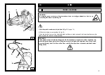
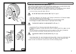
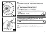
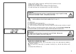
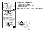
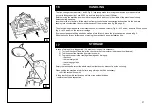
3) Lower the tool arm (14, fig. W) to work position until it gets hooked with the proper ratchet
4) Position the bead breaking disk level with rim (see fig. W)
5) Turn the chuck and, at the same time, move the disk forward with short steps following the rim profile, until
the first bead is fully detached. (Note: grease while doing this)
ATTENTION:
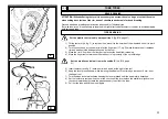
If the tyre has an inner tube, work very carefully and be prepared to stop the disk right after
the detachment of the bead to avoid damaging both valve and tube.
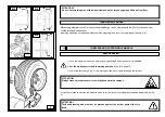
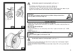
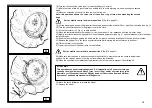
6) Repeat the operation but this time move the disk against the split-ring (see fig. Z, page 28) until the lock ring
gets released. Remove this by means of the proper lever (23, fig. Z, page 28) or with the help of the disk.
7) Remove the split-ring
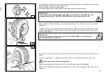
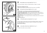
8) Move the tool arm (14, fig. W) from rim edge. Release the ratchet, tilt the arm to rest position and move
it to the inner side of the wheel.
9) Turn the tool by 180°
Lower the arm to work position.
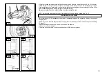
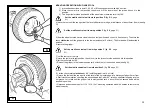
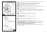
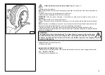
10) Turn the chuck and, at the same time, move the disk forward with short steps following the rim profile,
until the second bead is fully detached. (Note: grease while doing this). Keep on pushing the disk against
the tyre until half of it is out of the rim (see fig. K)
11) Tilt the tool arm to rest position
12) Lower the chuck until the tyre rests on the platform.
WHEELS WITH SPLIT RINGS
BEAD BREAKING AND REMOVING
WHEELS WITH 3-SEGMENT SPLIT RING
Set the mobile control unit in work position B
(fig. B/8, page
21)
1) Clamp the wheel on the chuck, as previously described, and make sure it is well deflated.
K
14
W
Содержание RGU588E
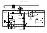
Страница 37: ...40 ELECTRIC AND HYDRAULIC DIAGRAMS ...


