16
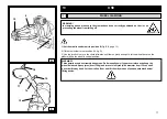
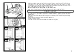
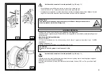
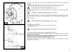
move the joystick (ref.1 fig. C page 9) leftwards (D): the chuck holder (8, Fig. A) must also move leftwards and, at
the same time, the tool holder (14, Fig. D) must move rightwards (getting far from each other);
repeat the operations (D) and (E) moving the switch lever (ref. 4, fig. C, page 9) to the other possible position:
movements must take place at a different speed (lower or higher according to the selected position, N or O).
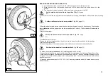
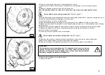
3) move the joystick (5, fig. C, page 9) UP: the chuck jaws (9, fig. A) must open; move the joystick DOWN: the jaws
must close.
Move the joystick (ref.1 fig. C page 9) rightwards (D): the chuck holder (8, Fig. A) must also move rightwards and, at
the same time, the tool holder (14, Fig. D) must move leftwards (getting close to each other).
Repeat the operations above moving the switch lever (ref. 3, fig. C, page 9): movements must take place at different
speed.
ATTENTION!
When the chuck holder moves down, it creates potential crushing points. Always work in the positions
given by this guide, keeping outside the action range of moving arms.
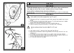
ATTENTION!
During the chuck jaws opening/closing movement there’s the risk of potential crushing points. Always
work in the positions given by this guide, keeping outside the chuck action range.
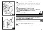
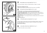
4) Press the pedal (ref.7, fig. C, page 9) in its right side: the chuck (9, fig. A) must rotate clockwise; press it in its left
side: the chuck must rotate counterclockwise.
Move the switch lever (3, Fig. C, page 9) DOWN and repeat the operations above: movements must take place at
a doubled speed.
5) Check the good functioning of hydraulic circuit:
- turn the switch (5, fig. C, page 9) UP and keep it that position until the chuck jaws have fully opened.
A
9
10
8
D
18
19
17
14
13
Содержание RGU588E
Страница 37: ...40 ELECTRIC AND HYDRAULIC DIAGRAMS ...


