33
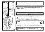
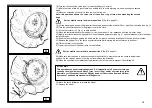
set the mobile control unit in work position B
(fig. B/8, page 21)
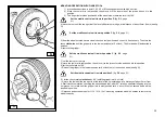
3) Set the tyre on the platform
4) Lower or lift the chuck as to perfectly centre rim with tyre
5) Move the chuck rightwards to let the rim enter the tyre
Move forward until the rim is fully inserted into tyre.
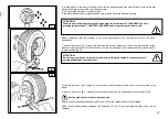
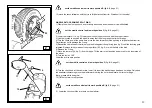
6) Set the bead wire on the rim (with the ledge ring mounted)
Note:
if rim and split ring have slits for fixing, these must coincide to each other.
set the mobile control unit in work position C
(fig. B/8, page 21)
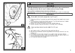
7) Move the tool arm to the outside, and then lower it to work position with the disk turned toward the
wheel.
Note:
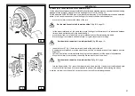
if the bead wire is not sufficiently set on the rim, move the chuck until the bead wire is level with the
disk. Move the disk forward (while turning the chuck) until the O-ring seat gets uncovered.
8) grease the O-ring and set it into its seat
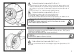
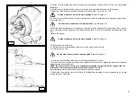
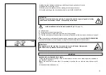
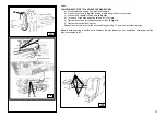
9) Set the lock ring on rim with the help of the disk as shown in Fig. Y
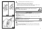
Move the tool arm to rest position and close the chuck jaws completely, taking care to hold the wheel to
prevent it from falling off
ATTENTION!!
This operation can be extremely dangerous. Do it manually only if you are certain you can
keep the wheel balanced. Heavy tyres (over 110kg) and/or oversize tyres (with diameter over
130cm) shall never be lifted by hand. Let them roll on floor and lift them by means of an
adequate mechanical lifting device.
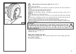
10) Move the chuck to release the wheel
11) Remove the wheel
set the mobile control unit in work position C
(fig. B/8, page 21)
ATTENTION!
Do not inflate the tyre when the wheel is still mounted on the chuck. Tyre inflation can be
extremely dangerous, therefore it must be performed with the wheel placed inside a proper
inflating cage, for the safety of the operator.
Y
Содержание RGU588E
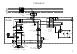
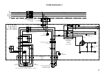
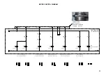
Страница 37: ...40 ELECTRIC AND HYDRAULIC DIAGRAMS ...

