background image

47

1)

 Portare il braccio porta autocentrante in posizione di fuori lavoro. 

Se il cerchio è stato smontato dall'autocentrante ribloccarlo come 

descritto nel paragrafo "BLOCCAGGIO DEL CERCHIO".

N.B.:

 Se la ruota ha la camera d'aria è necessario posizionare il 

cerchio con l'asola per la valvola in basso (a ore 6). 

2)

 Lubrificare i talloni del pneumatico e il cerchio con l' apposito 

grasso.

3) 

Traslare la pedana mobile all'esterno in modo da poter farvi salire 

sopra il pneumatico. 

N.B.:

 Se la ruota ha la camera d'aria è necessario posizionare il 

pneumatico con la valvola in basso (a ore 6). 

4) 

Abbassare od alzare l'autocentrante in modo da centrare esatta-

mente il cerchio rispetto al pneumatico.

5) 

Traslare la pedana verso l'interno in modo da far entrare il cerchio 

nel pneumatico.

ATTENZIONE: 

Per pneumatici con camera d'aria è necessario fare 

rientrare la valvola per non rischiare di danneggiarla.

Avanzare fino al completo inserimento del cerchio nel pneumatico.

6)

 Portare il braccio porta utensili sul lato esterno quindi abbassarlo 

in posizione di lavoro con il disco stallonatore rivolto verso la ruota.

N.B.: 

Nel caso il pneumatico non sia sufficientemente inserito sul 

cerchio, muovere l'autocentrante fino a portare il tallone del pneuma-

tico in corrispondenza del disco stallonatore. Avanzare con il disco 

(e contemporaneamente ruotare l'autocentrante) fino al completo 

inserimento.

7) 

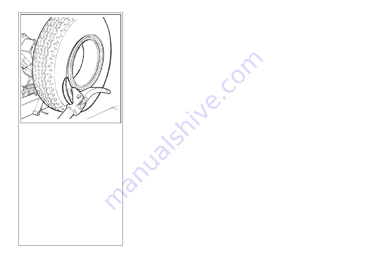
Posizionare il cerchietto sul cerchio, quindi montare l'anello di 

bloccaggio aiutandosi con il disco stallonatore come in Fig. 43.

8) 

Portare il braccio porta utensili in posizione di fuori lavoro e rimuo-

vere la ghiera di bloccaggio del cerchio, avendo cura di sostenere la 

ruota per evitarne la caduta.

9) 

Traslare la pedana per liberare la ruota dall'autocentrante.

10)

 Rimuovere la ruota.

1) 

Move the tool carrier arm to its non-working position. If the rim 

has been removed from the spindle, put it back on the spindle as 

described in the section on “LOCKING THE RIM”.

If the tyre has the inner tube, position the rim with the valve slot at 

the bottom.

2) 

Lubricate both beads and the rim with proper grease.

3) 

Move the platform outward so as to place the tyre on it.

NOTE: 

If the tyre has the inner tube, position the rim with the valve 

slot at the bottom.

4) 

Lower or lift the spindle to match rim and tyre accordingly.

5) 

Move the platform inward so as to let the rim into the tyre.

CAUTION!  

If the tyre has the inner tube, push the valve inside so 

as not to damage it.

Go on moving the platform until the rim is completly positioned into 

the tyre.

6) 

Bring the tool carrier arm to the outside plane and lower it to its 

work position with the disk towards the wheel.

NB: 

If the tyre is not inserted sufficiently on the rim, move the spindle 

until the tyre bead is by the disk. Bring the disk forward (with the 

spindle turning) until it is completely inserted.

7) 

Put the split-ring on the rim and then install the locking ring with 

the help of the disk as shown in Fig. 43.

8) 

Move the tool carrier arm to its non-working position and remove 

the ring locking ring nut. Take care to support the wheel so as to 

prevent it from falling off.

9) 

Move the platform to free the wheel from the spindle.

10) 

Remove the wheel.

7.5.2_Montaggio con UTENSILE DOPPIO 

7.5.2_Tyre mounting with DOUBLE TOOL

Fig.43

Содержание RGU 264 E

Страница 1: ...LE LKW REIFENMONTIERGER T MANUALE DI ISTRUZIONI PER L USO E LA MANUTENZIONE USE AND MAINTENANCE INSTRUCTIONS MANUAL D INSTALLATION D UTILISATION ET D ENTRETIEN INSTALLATION BEDIENUNG UND WAR TUNG ED 0...

Страница 2: ...ION DE CONFORMITE CE CE BEREINSTIMMUNG DECLARACION CE DE CONFORMIDAD al quale questa dichiarazione si riferisce E CONFORME ALLE SEGUENTI DIRETTIVE to which declaration refers is in conformity with the...

Страница 3: ...ung mu gem der folgenden Vorschrift durchgef hrt werden e le disposizioni di Legge del Paese di destinazione della macchina apparecchiatura as well as with the national laws in force in the Country of...

Страница 4: ...ine pour ce service contacter le constructeur ou les revendeurs autoris s Die vorliegende Maschine Ger t f llt in den Vorschriften der 2002 96 CE Richtlinie und kann nicht als allgemeiner Stadtm ll so...

Страница 5: ...UMERO DI MATRICOLA Nr faciliter il servizio da parte dell assistenza tecnica Questi dati si trovano sulla targhetta adesiva applicata sul retro dello smontagomme di cui riportiamo un FAC SIMILE per ma...

Страница 6: ...u sera consid r impro pre et irraisonn et par cons quent sous l enti re responsabilit de l op rateur Wir danken Ihnen f r den Einkauf eines unserer Reifenmontierma schinenpalette f r LKW Autobusse und...

Страница 7: ...m 7A Cono di bloccaggio 200 300 mm 8 Ghiera di bloccaggio a manovella 9 Utensile a rullo per montaggio smontaggio 10 Pedana scorrevole supporto ruota 11 Supporto porta coni flange e attrezzi da lavoro...

Страница 8: ...ue 6 A Bride mobile de blocage roue 7 C ne de blocage 100 200 7 A C ne de blocage 200 300 8 Manivelle de blocage 9 Rouleau de montage d montage 10 Plateforme coulissant de support roue 11 Support port...

Страница 9: ...r essere ritenuto colpevole di eventuali danni derivati o riconducibili agli atti suddetti Non possibile utilizzare lo smontagomme in ambienti con atmosfera potenzialmente esplosiva a meno che non si...

Страница 10: ...osive moins qu il s agit d une version sp ciale 3 ALLGEMEINES 3 1_Normes g n rales de s curit Die Reifenmontiermaschine eignet sich ausschlie lich zur Montage Demontage von Reifen auf aus Felgen Die M...

Страница 11: ...abbassa braccio porta flangia di bloccaggio Cod 3008614 Decalco max pressione centralina idraulica Cod 3008616 Decalco indicazioni olio Cod 3010065 Decalco dati centralina idraulica Cod 3009565 Decal...

Страница 12: ...Decalco rep re huile Decalco donn es unit hydraulique Decalco rotation moteur 3 1_Normes g n rales de SECURITE 3 1_Allgemeine SICHERHEITShinweise Cod 3005410 Spannungsanwesenheit Cod 3005421 Quetschun...

Страница 13: ...che sia protetta da una tettoia per ripararla dalla pioggia E proibita l installazione dello smontagomme in ambienti con atmosfera esplosiva 6 INSTALLAZIONE 6 1_Scelta del luogo di installazione Fig...

Страница 14: ...re la pluie par un abri DEFENSEd emploienmilieuxayantatmosph reexplosive Die Reifenmontiermaschine in urspr nglicher Verpackung transpor tieren und in der angegebenen Stellung halten Zur Verlagerung d...

Страница 15: ...griglia elettrosaldata strato di ghiaia 100 50 150 8mm 16 16 16 Fig 6 The universal tyre changer must be installed on a level concrete floor at least 15 cm thick with a minimum concrete quality of B2...

Страница 16: ...n a pas ces caract ristiques il faut pr voir des fondations appropri es au dessous des points d appui La surface sur laquelle le d monte pneus universel sera install doit tre parfaitement plate Toute...

Страница 17: ...Se fosse necessario cambiare la tensione di funzionamento della macchina occorre intervenire sulla morsettiera come da schema elettrico a pag 62 Collegare la macchina alla rete elettrica e controllare...

Страница 18: ...te running direction it is necessary to have two wires inverted in the plug by expert staff The motor run made in the opposite direction if longer than a few seconds can cause irreparable damages to t...

Страница 19: ...ccia continua per far ruotare la flangia 6 in senso ANTIORARIO Azionale la leva 2 nel senso indicato dalla freccia tratteggiata per far ruotare la flangia 6 in senso ORARIO Azionare la leva 3 nel sens...

Страница 20: ...le sens indiqu par la fl che continue pour faire tourner la bride 6 en sens ANTIHORAIRE Actionner le levier 2 dans le sens indiqu par la fl che hachur e pour faire tourner la bride 6 en sens HORAIRE...

Страница 21: ...nticare di consultarlo Per arrestare lo smontagomme in condizioni di emergenza Ruotare l interruttore generale sulla posizione 0 Staccare la spina elettrica Utilizzare solamente accessori e ricambi or...

Страница 22: ...d urgence tourner l int rrupteur g n ral sur 0 d brancher la fiche lectrique N utiliser que des accessoires et des pi ces de rechange d origine 7 BETRIEB 7 1 Allgemeine Sicherheitshinweise Die Nichtb...

Страница 23: ...e il perno anti rotazione della flangia 20 nella parte inferiore del cerchio Far combaciare il perno anti rotazione 20 con uno dei fori di bloccaggio del cerchione come indicato in fig 15 Inserire sul...

Страница 24: ...n position hors travail En actionnant le levier 3 loigner la plate forme mobile 10 de la bride et y positionner la roue en la tenant en position verticale Cette op ration peut tre extr mement dangereu...

Страница 25: ...senso ORARIO se si opera sul fianco esterno o in senso ANTIORARIO se su quello interno 6 Allontanare il braccio porta utensile dal cerchio sganciare il cricchetto sollevare il braccio in posizione di...

Страница 26: ...rocher dans la deuxi me position de travail Ne pas tenir les mains sur l outil lors de son reposition nement en travail afin d eviter tout possible crasement entre l outil m me et la roue 7 Faire tour...

Страница 27: ...o a brevi scatti 6 Avanzare fino al completo distacco del tallone Per agevolare l operazione con la ruota in movimento lubrificare il tallone e la balconata del cerchione con l apposito grasso Fig 17...

Страница 28: ...d de la jante par la graisse en dotation fig 17 1 17 2 Pr ter attention particuli re ne pas s craser les doigts entre le pneu et l outil Afin d eviter tout risque faire tourner en sens HORAIRE lors de...

Страница 29: ...Prestare particolare attenzione a non schiacciarsi le dita tra il pneumatico e l utensile Per evitare qualsiasi rischio ruotare in senso ORARIO se si opera sul fianco esterno o in senso ANTIORARIO se...

Страница 30: ...les doigts entre le pneu et l outil Afin d eviter tout risque faire tourner en sens HO RAIRE lors des op rations sur le bord ext rieur et en sens ANTIHORAIRE lors des op rations sur le bord int rieur...

Страница 31: ...are il pneumatico fino a portare la pinza nel punto piu basso Il primo tallone dovrebbe essere entra to Fig 24 8 Posizionare il rullo a 4 5 mm di distanza dal cerchio e premere sul secondo tallone del...

Страница 32: ...d and turn the tyre until the pliers is in its lowest point First bead should be set in position fig 24 8 Position the roller at a distance of 4 5 mm from the rim and press on second tyre bead in orde...

Страница 33: ...il pomolo di bloccaggio e ruotarlo di 180 8 Agendo sulle leve 3 4 muovere l utensile fino a portare il suo punto rosso di riferimento in asse con il bordo esterno del cerchio ad una distanza di 5 mm d...

Страница 34: ...xt rieur de la jante une distance de 5 mm de la jante m me fig 28 9 Tourner le pneu en sens horaire jusqu porter la pince dans le point le plus bas Le premier talon doit tre rentr En cas de difficult...

Страница 35: ...gonfiare il pneumatico con la ruota ancora montata sull autocentrante Il gonfiaggio pu essere pericoloso perci deve essere effettuato in aoopositi luoghi di sicurezza Fig 30 Fig 31 14 Position the pli...

Страница 36: ...e sur le centreur Le gonflage peut tre dangereux et il doit donc tre effectu dans des endroits appropri s et en conditions de s curit 14 Die Zange kaum auf das Spitzewerkzeug stellen Abb 30 15 Den Rei...

Страница 37: ...tra dell utensi le 6 Mantenendo la leva premuta abbassare la ruota fino a portare il bordo del cerchio ad una distanza di circa 5 mm dall utensile a becco Fig 32 7 Girare la ruota in senso antiorario...

Страница 38: ...tion de hors service Abaisser le mandrin pour appuyer le pneu sur la plate forme mobile qui l g rement avanc e vers l ext rieur cr era l espace n cessaire pour extraire la chambre air 9 Extraire la ch...

Страница 39: ...4 Set the tyre onto the platform and lower the spindle keeping the clamp at the highest point to hook the first bead to the clamp 10 Traslare il braccio portautensile sul lato interno della ruota ruot...

Страница 40: ...le plus haut pour accrocher le premier talon la pince m me 10 Den Werkzeugtragarm nach Radinnenseite verlegen das Werkzeug um 180 verdrehen und den Arm in Arbeitsstellung bringen Das Werkzeug zwische...

Страница 41: ...camera d aria come indicato in fig 36 Introdurre la valvola nel foro e fissarla mediante la sua ghiera 15 Introdurre la camera d aria nel canale del cerchio N B per agevolare l operazione consigliabi...

Страница 42: ...reux de la jante N B pour faciliter l op ration il est conseill de faire tourner en m me temps le mandrin vers la droite 5 Die Felge mit dem angehakten Reifen heben und 15 20 cm im Gegenuhrzeigersinn...

Страница 43: ...orm 27 Let the wheel lean on the platform and check that the valve is perfectly centered with the outlet hole If not turn the spindle slightly to adjust the position Fix the valve by means the locking...

Страница 44: ...ani re lib rer la roue du mandrin et enlever la roue 16 Das Spannfutter verdrehen bis das Ventil unten steht 17 Den Schlauch leicht aufpumpen bis er keine Falten mehr aufweist um zu verhindern da er w...

Страница 45: ...n l apposita leva 22 o con l aiuto del disco stallonatore Rimuovere il cerchietto 6 Allontanare il braccio porta utensili 17 dal bordo del cerchio Sganciare il cricchetto e sollevare il braccio in pos...

Страница 46: ...er der Abdr ckscheibe herausziehen und Spaltring entfernen 6 Den Werkzeugtragarm vom Felgenrand entfernen Den Sperrkegel ausrasten und den Arm in Raststellung hochklappen Den Werkzeugtra garm nach Rad...

Страница 47: ...o porta utensili in posizione di fuori lavoro e rimuo vere la ghiera di bloccaggio del cerchio avendo cura di sostenere la ruota per evitarne la caduta 9 Traslare la pedana per liberare la ruota dall...

Страница 48: ...ue du mandrin 10 Enlever la roue 1 Den Spannfutterarm in Raststellung bringen Wenn die Felge vom Spannfutter heruntergenommen worden ist mu sie wieder aufgespannt werden wie im Abschnitt RADAUFSPANNEN...

Страница 49: ...rarsi che la stessa sia sgonfia 2 Abbassare il braccio porta utensili in posizione di lavoro fino a che si sar agganciato con l apposito cricchetto 3 Agendo sul manipolatore posizionare la ruota in mo...

Страница 50: ...late forme mobile 10 sous le pneu 1 Das Rad wie vorstehend beschrieben auf dem Spannfutter auf spannen Sicherstellen da die Luft aus dem Rad abgelassen ist 2 Den Werkzeugtragarm in Arbeitsstellung sen...

Страница 51: ...aggio potrebbero causarne il distacco e la conseguente caduta 17 Sollevare la ruota 18 Riportare il braccio porta utensili in posizione di lavoro 19 Posizionare l autocentrante in modo che il disco st...

Страница 52: ...sitionnement et du blocage peut provoquer le d collement et la chute 12 Das Spannfutter senken bis wann der Reifen die Schiebeb hne ber hrt 13 Die Schiebeb hne nach au en verlegen und den Reifen mit...

Страница 53: ...e di fuori lavoro e rimuovere la ghiera di bloccaggio del cerchio avendo cura di sostenere la ruota per evitarne la caduta 10 Traslare la pedana per liberare la ruota dall autocentrante 11 Rimuovere l...

Страница 54: ...mani re lib rer la roue du mandrin 11 Enlever la roue 1 Den Spannfutterarm in Raststellung bringen Wenn die Felge vom Spannfutter heruntergenommen worden ist mu sie wieder aufgespannt werden wie imAbs...

Страница 55: ...re changer in a new place a lift truck must be available on site Disconnect the power supply Set up the lifting hanger again Lift the tyre changer using a lifting belt and place it in the new site Rem...

Страница 56: ...eus dans un nouvel endroit il faut disposer d un chariot l vateur D brancher l alimentation lectrique Remonter l trier de levage Soulever le d monte pneus moyennant une courroie appropri e et le posit...

Страница 57: ...11 1_General precautions Avoid direct and prolonged contact with skin Avoid any vaporization of oil in the atmosphere Avoid oil splashes Wear suitable clothes gloves and protective glasses against po...

Страница 58: ...et prolong avec la peau Eviter toute n bulisation d huile dans l atmosph re Eviter les gicl es Mettre des v tements appropri s des gants et des lunettes en cas de gicl es Ne pas utiliser des chiffons...

Страница 59: ...tensione della cinghia del motore elettrico Se fosse necessario regolarne la tensione togliere il carte di protezio ne in plastica allentare i dadi X indicati in figura 48 e tendere la cinghia X X Ma...

Страница 60: ...delacourroiedumoteur lectrique Pourr gler la tension enlever d abord la protection en plastique d sserrer les crous X indiqu s en fig 48 et tendre la courroie X X Fig 48 T Fig 47 13 WARTUNG Die Wartun...

Страница 61: ...sare in sostituzione del rullo tubeless per il montaggio smontaggio di pneumatici con camera d aria Leva alzatallone lunga inclusa art 206 98 Art 205 98 Art 206 98 Cod 9209551 Additional arm with tube...

Страница 62: ...erkzeug Dadurch wird die Montage Demontage von Reifen mit Schlauch erlaubt Inkl von langem Wulstabdr ckhebel Cod 9209551 art 205 98 Cod 9209552 art 206 98 Cod 9209551 art 205 98 Cod 9209552 art 206 98...

Страница 63: ...n M1 Moteur lectrique pompe hydraulique F1 F2 Disjoncteur thermique 4 0 6 3A Q1 Sectionneur 12A C1 Inverseur 3PH NOTA Cambiando la tensione del motore occorre tarare la TERMICA con i dati di targa rip...

Страница 64: ...M1 Moteur lectrique pompe hydraulique F1 F2 Disjoncteur thermique 4 0 6 3A Q1 Sectionneur 12A C1 Inverseur 3PH NOTA Cambiando la tensione del motore occorre tarare la TERMICA con i dati di targa ripo...

Страница 65: ...ZA Flange holding arm cylinder VLP Pressure limiting valve PI Hydraulic pump M Motor F Filter TS Breather cap D2C Double lever distributor ZC Schlittenzylinder ZA Flanschtragarmzylinder VLP Druckminde...

Страница 66: ...Cod 3010008 FASEP 2000 srl Via Faentina 96 50030 RONTA FI ITALY Tel 39 055 8403126 Fax 39 055 8403354 E mail info fasep it http www fasep it...

Отзывы:

Похожие инструкции для RGU 264 E