


MP3020
INSTALLATION MANUAL - EN
Edition 1.0 May 2021
Pag. 4 di 12
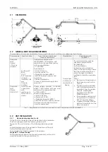
2.1
DIMENSIONS
2.2
GENERAL ELECTRICAL REQUIREMENTS
The requirements for correct installation for any application (unit, wall, floor or ceiling) are the following:
Power supply
PowCer cable
Type of power supply and
safety requirements
Classification
Compliance with
IEC 60601-1
Complete
light
version
17-24 Vac
50/60 Hz
2 x 0.5 mm2
300 V
105°C
PVC insulation
diameter
insulation 1.85
mm
Only use
certified
terminals and
connectors
with
resistance to
flame VW-1 or
similar.
Transformer complies with
IEC/EN 60601-1 third edition with
protection of phase of secondary
with appropriate fuse:
•
T1.6AL 250V
Requirements:
• Output: 24 V ac;
• Power: min 26 VA
• Dielectric strenght> 4000 V.
• 2MOPP between primary and
secondary
• Thermal protection
In case of permanent application
see note 1
Component
built-in part
of a Medical
Device
The medical system must be
declared compliant with
IEC/EN60601-1
by the installation
technician or manufacturer.
Note for the Service Eng.: assure
that the combined version on
which the light is installed is
certified to install the complete
light.
Note 1:
the fuse must be placed on
the phase and not on the
neutral.
The lamp must be installed
with a multipolar device to
separate it from the supply
network, meeting the
requirements of IEC/EN
61058 standards.
This separation device must
be approved to withstand
4KV of transient voltage
A green status light shall be
inserted to indicate that the
lamp is powered.
Complete
light
version
25-33 V DC
Power supply conform to IEC/EN
60601-1 third edition with one pole
protected by appropriate fuse:
T1,25A L 250V
Minimum requirements:
Output: 32 Vdc
Power: min 15 VA;
Dielectric strenght > 4000 V;
2 MOPP between primary and sec.
Continuous protection from short
circuit or overcurrent
Tab 1 – Requirements for electrical connection and compliance with IEC/EN 60601-1.
2.3
UNIT INSTALLATION
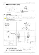
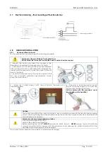
2.3.1
Mechanical connection to unit
Fit the Post into the seat of the unit dedicated to the Luminaire.
The Post is designed with the following tolerance: F7
The seat of the unit must be of the following tolerance grade:
H7
Lubricating grease must be applied to the surface of the post
before the connection is done.
Faro suggests the following grease to be applied:
Molykote 111 silicon Grease
.
With a digital level, ensure the connection element on the unit is
perfectly parallel to the ground (max 2°)
Содержание MP3020
Страница 1: ......


