


MP3020
INSTALLATION MANUAL - EN
Edition 1.0 May 2021
Pag. 11 di 12
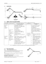
2.7
Electrical drawing – floor mounting without transformer
2.8
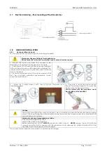
HEADLIGHT INSTALLATION
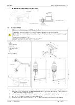
2.8.1
Mechanical Requirements
For the mechanical connection apply the following procedure:
Warning for danger of falling of suspended mass.
Strictly Follow the instruction to avoid the head to detach from the support.
1 -Support the head and insert the washers in the
threaded pin according to the sequence in the figure.
2 - Insert ring nut G according to the sequence indicated
in the picture and screw in with adequate equipment. The
ring nut must be screwed in to give the correct rotational
force to the head.
3 – As term of reference the nut G must be screwed at 0,8
Nm. Use a suitable calibrated dynamometric torque
wrench to screw the nut.
4 – Screw the 2 safety screws F until the cut (A) into the brass nut is
completely closed.
4 – take care to leave free space around
the nut G and the support S, to avoid any
friction when the head is rotating.
Fail to comply with this procedure could
lead in falling of the headlight.
Caution
The central arm without the head load tends to rise in a sudden manner with the risk of knocking against
parts of the body. During the entire installation, keep the central arm in position and do not release it until
head installation is complete.
Warning for danger of suspended mass falling
Only use screws supplied by FARO.
Screw in the safety screws together.
Before removing the nut (G)
ALWAYS
remove the safety screw F.
NEVER
unscrew the nut (G) with the
screws F mounted. Fail to comply with this procedure could damage the plastic threated PIN of the
headlight with possible detach of the headlight.
Once mechanical connection is complete, complete electrical wiring.
Содержание MP3020
Страница 1: ......


